Intended Changes
Known fixes and planned improvements. P0 is reserved for broken features; higher numbers are progressively lower priority, with P4 used for nice-to-have improvements. Click any part thumbnail to inspect its current interactive 3D model.
| Priority | Change | Affected BOM items |
|---|---|---|
| P0 Broken feature | Stator's four NEMA-bracket holes are too small for an M3The four holes the NEMA bracket bolts into are Ø2.40 mm and 10 mm deep. M3's minor (thread-root) diameter is 2.459 mm, so the hole is already narrower than the root before print tolerance takes another 0.1-0.2 mm off it, and the screw has to form a full-depth thread through 10 mm of plastic. It cams out or splits the boss instead, so the bracket cannot be fastened to the stator as printed. Every other M3 thread-forming hole in this assembly is Ø2.80 — the rotor's six, the light post's five, and four more in this same stator — so Ø2.40 is the odd one out inside its own part, which reads as a CAD slip rather than an intent. The fix is to open the four to Ø2.80 in CAD. Reported by aleph1111/christoph from a build; measured off the pinned stator STL. Tracked as sorter-v2 issue #405. | |
| P1 Broken feature | Merge the two chute bearing holders into one partThe chute door module asks for two different printed parts, a left bearing holder and a right one, where one part printed twice does the whole job. They are the same geometry. Measured off the two master STLs: a proper rotation of exactly 180.000 degrees about the flange face normal (0, 0.906, 0.423) maps one onto the other with a maximum deviation of 0.065 mm and a mean of 0.004 mm, and the transform's determinant is +1, so no handedness is involved. The only asymmetry in either part is 0.05 mm, between two of the three M3 insert pockets, at 17.35 mm and 17.40 mm from the bore centre. The machine should carry one holder and print it twice, which drops the printed part count by one. Nothing about the assembly changes: the two bearing seats face outward either way. The two ids are interchangeable as they stand. Which id survives, and what a single holder should be called, are open questions. Tracked as sorter-v2 issue #569, with the catalog side in #570. | |
| P2 | Make bin retainers snap onRedesign the left and right bin retainers to snap on and remove their screen holes. Each retainer currently uses two screws, two nuts, and two washers, so this could eliminate roughly 200 purchased pieces from a machine build. | |
| P2 | NEMA 23 chute motor screws have no retention against vibrationThe four M5 x 12 screws holding the NEMA 23 chute stepper onto its bracket are driven upward from below, since the bracket is already mounted to the underside of the Top plate by the time the motor goes on. Nothing but the screws' own friction holds that joint, so machine vibration backs them out over time and they can drop out completely. The fix needs some form of positive retention at the joint (captive nut/washer, a retaining boss or clip, or reworked bracket/motor mount geometry) rather than relying on threadlocker. Reported by Nafets from a machine with 280k+ pieces sorted, diagnosed by barthel. Tracked as sorter-v2 issue #411. | |
| P3 | Improve the interface bracket designMake the screws for the vertical aluminum extrusion easier to install and remove the interface bracket's unnecessary bulk. | |
| P3 | Reverse chute doorMove the chute door to the other side so the flap closes the open funnel hole. This affects the chute as a whole and all of its parts. | |
| P3 | Update interface lazy-Susan fasteners to M5Update the four printed parts in the top and bottom interface lazy-Susan joints from M4 to M5 countersunk screws and matching M5 heat-set inserts. The upper interface holes are currently too close together and should be corrected as part of the change. | |
| P3 | Split the top plate into a supported puzzleDivide the top plate into interlocking puzzle-like sections around a single inner structural support ring, so the plate can be made in smaller pieces while keeping primary support around the center. | |
| P3 | Count the bins and funnels in the machine treeThe five bin parts and the two funnels are in no assembly, so the machine tree rolls them up as 0 and the Machine assembly page shows a machine with no bins in it. The 3D printed parts tab counts them correctly from their own quantities, so nothing anybody prints or buys is wrong, and neither part takes a fastener, so no hardware total is affected. The fix is not a data edit. Both are variant_group parts chosen per layer (third or half), and a tree line resolves its quantity from lineQty(line, layers), which knows the layer count and nothing else. Placing them needs a way for a line to express a per-layer variant, and a decision about what a mixed stack of third and half layers means to a node that is instantiated per layer. Found 2026-09-05 while reconciling the tree against the printed-parts and framing models, and deliberately left out of #545 and #561. | |
| P4 | Keep the interface spacer in its slotThe interface spacer falls off the aluminum profile it slots into too easily. Improve its retention so it stays seated during handling and assembly. |
Completed Changes
Resolved fixes and improvements remain here as a record of what changed. They no longer mark parts as broken or subject to change.
| Status | Change | Affected BOM items |
|---|---|---|
| Complete Sep 26, 2026 | Secure the Mean Well 24V PSU box capReplaced the three-plate box and its cap with the five-piece PSU housing, whose two lids screw down. | |
| Complete Sep 8, 2026 | The output guide and the C4 finned rotor cannot both be fittedC-channel 4 carried both the finned rotor unit and the Short and Angled Output Guide, and the two occupy the same space. The guide's inner face sits at r 67.82 mm; the finned rotor's five fins reach out to r 85.4 and sweep up to 21.2 mm past that face over the band z 8 to 29, striking the guide at 24 of 72 rotations. The faceted rotor used on C1 to C3 clears the same guide by 1.5 to 1.8 mm along its whole height, which is the clearance the guide is dimensioned to. Resolved by taking the guide off C-channel 4: it had none until e22fce30 (#534, 2026-09-02) consolidated all four channels onto one shape. Reported from a build by Extremetaz. | |
| Complete Sep 7, 2026 | Ribbon cable clamp does not seat flat on the cage bracketThe clamp could not close on the ribbon cable: the lip at its lower end is a hook meant to go over the bottom edge of the cage post, but the post's underside sat 1.43 mm above where the lip could reach, so it landed on the post's bottom edge instead of clearing it and pivoted loose on its single M3. Fixed by raising both cage brackets' underside ~2 mm (interface-cage-bracket and interface-cage-bracket-cable, both v2), which was also the fix for a separate problem found along the way: every bracket's v1 was exported from a 25mm-tall Onshape branch ('temp catcher wall') that had diverged from the 23mm-tall 'main' branch the rest of the cage now uses. The lip now clears the post's underside by 0.57 mm. ribbon-cable-clamp itself is unchanged. Reported from builds by barthel, zed0 and Jon, design intent from ChrisKiepfer, root-caused and fixed with Spencer. Tracked as sorter-v2 issue #403, fixed in PR #589. | |
| Complete Sep 2, 2026 | Replace prototype C-channel supportsReplace the current C-channel legs, feet, and leg extensions. These prototype parts work, but they are unstable and will be replaced with improved designs. | No preview available |
| Complete Sep 2, 2026 | Widen the C-channel output guideUpdate the output guide so large pieces that are still within specification can pass through the C-channel exit. | |
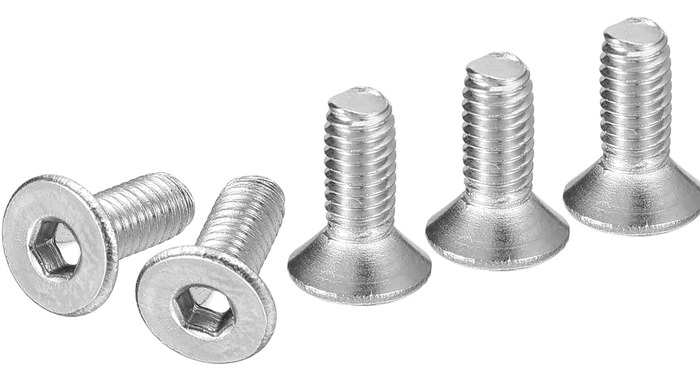
| Complete Sep 1, 2026 | Output gear to rotor screw does not reach the rotorThe six screws holding the Output gear (130T) to the rotor were specified as M3 x 8 mm countersunk. The gear is 8.00 mm thick at the bolt circle and a countersunk screw's length is measured over its head, so an M3 x 8 seated flush in the countersink ends level with the gear's top face and takes no thread in the rotor at all. Fit M3 x 12 mm countersunk for now: 4.0 mm of thread in the rotor's 5.0 mm flange, 1 mm short of breaking through the far side. Whether the joint settles as a 12 mm screw or the gear boss changes is still to be decided, so treat the length as provisional. Reported from a build by aleph1111/christoph and scres; measured off the pinned output-gear and rotor STLs. Fixed: both rotor units call for M3 x 12 mm countersunk, with the reason recorded on the joint (441d9114, #515, 2026-09-01), and the docs page was corrected in #378. | |
| Complete Aug 18, 2026 | Fix bulk cap dovetailIncreased the dovetail clearance so the bulk cap slides onto the stator more easily and seats without excessive force. | |
| Complete Aug 18, 2026 | Fix the interface bracket fitAdded 0.2 mm clearance on every side of the horizontal aluminum spoke. |