Hardware
Screws
 6mm
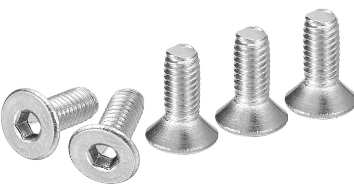
6mm M3 × 6 mm countersunk
Secures the limit switch hammer into the top interface chute mount from below, into the hammer's M3 insert.
The ×1 is the top-interface count (limit-switch hammer). Screws used elsewhere on the machine aren't tallied here yet.
 6mm
6mm M3 × 6 mm socket/button head
Holds the layer adapter board down on the chute core's heat inserts.
8mm M3 × 8 mm countersunk
The workhorse M3 screw, used all over the machine wherever a flush head is wanted.
12mm M3 × 12 mm countersunk
The long M3 countersunk. Used all over the machine.
 12mm
12mm M3 × 12 mm socket/button head
Mounts the cable clamp to the interface, and fastens the camera extension into the Camera & LED insert.
 16mm
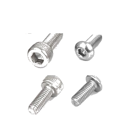
16mm M3 × 16 mm socket/button head
Holds the roller lever limit switch to its housing. 2 screws, into the housing's inserts.
16mm M3 × 16 mm countersunk
Bolts the NEMA 17 stepper to the NEMA bracket, into the stepper's tapped face holes. 3 per C-channel.
20mm M3 × 20 mm countersunk
Joins the C-channel light post to the NEMA bracket. Threads straight into the printed post. No insert and no nut.
 40mm
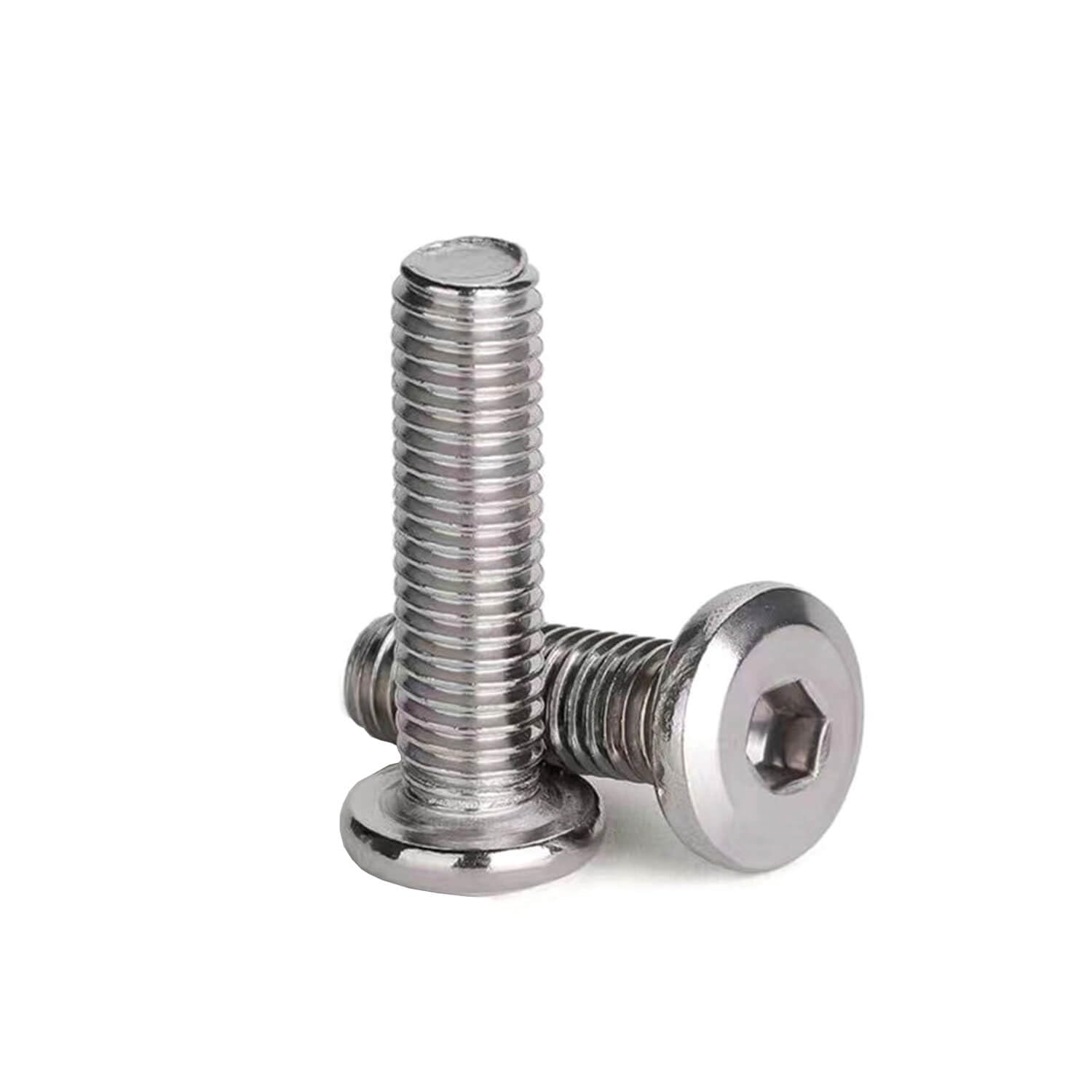
40mm M3 × 40 mm flat head
The long M3 that clamps the two cable-clamp halves together at the top interface, threading into an M3 nut in the pocket in the Cable clamp (outer).
 12mm
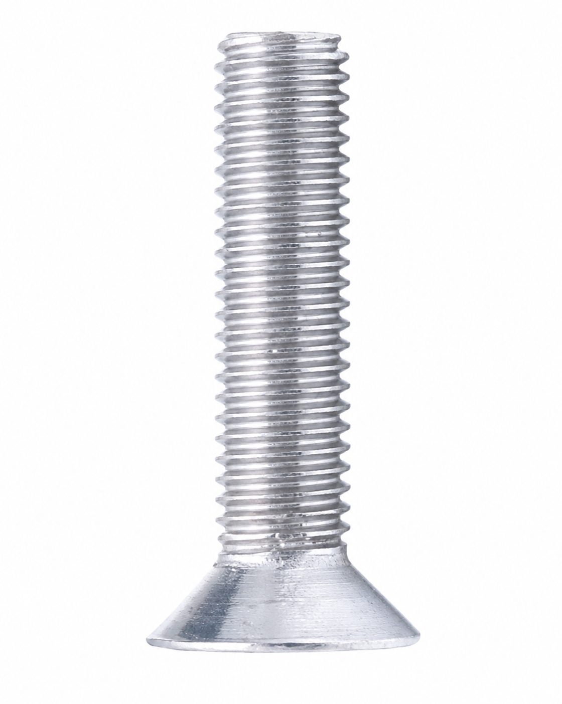
12mm M4 × 12 mm countersunk
Bolts the power supply into the PSU box's shell rear tray, 4 per box. Use this length only here. The lazy Susans take the M4 × 16 instead.
16mm M4 × 16 mm countersunk
Bolts each lazy Susan to the parts either side of it, 4 a side, into M4 inserts. 2 lazy Susans per machine.
8mm M5 × 8 mm countersunk
Loosely fixes the limit-switch interface bracket's extrusion into the interface rib while aligning it, into a T-nut.
A snug fit here, it barely reaches the T-nut. Opening the countersink a little and tightening firmly gets the head to sit flush. The ×6 is the top-interface count (1 per interface bracket); screws used elsewhere on the machine aren't tallied here yet.
 12mm
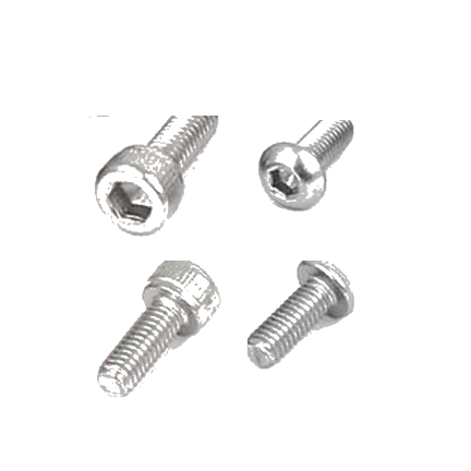
12mm M5 × 12 mm socket/button head
Holds the NEMA 23 stepper onto the interface bracket.
 16mm
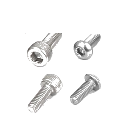
16mm M5 × 16 mm socket/button head
The most-used M5 in the machine: every external bracket, every bin bracket, every interface rib, every lazy Susan extrusion mount.
Designed to self-tap into printed plastic wherever it lands in an external bracket or the upper fixed section, no nut and no insert there.
 20mm
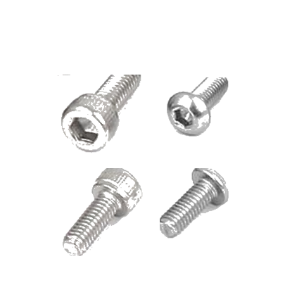
20mm M5 × 20 mm socket/button head
Mounts the chute limit switch assembly to the interface frame, into T-nuts.
22mm M5 × 22 mm countersunk
Bolts the interface bracket assembly and all six interface brackets down through the laser-cut top plate (holes S2/S3, then I1–I6 and O1–O6).
The top plate's laser-cut holes aren't countersunk, so where a flush head won't seat an M5 × 20 button head is used instead. The ×14 is the top-interface count (2 to the top plate, 12 through the bracket holes); screws used elsewhere on the machine aren't tallied here yet.
 30mm
30mm M5 × 30 mm socket/button head
Attaches the cable cage to the six interface brackets.
35mm M5 × 35 mm flat head
The long screws that stack the cable cage together, and that bolt the plywood top plate down onto the interface brackets.
Washers
M5 washer
Plain M5 flat washer, 5.3 mm hole, 10 mm outer diameter, 1 mm thick. Put one under the head of each M5 screw that bolts an electronics enclosure to the 2020 frame.
Nuts
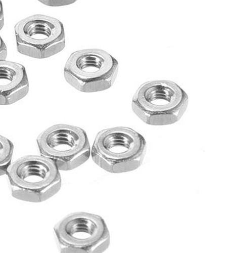
M3 nut
Plain M3 hex nut. Backs the camera-arm screws and the cable clamp's long screw.
M5 nut
Plain M5 hex nut. Holds the cable cage's six long screws on.
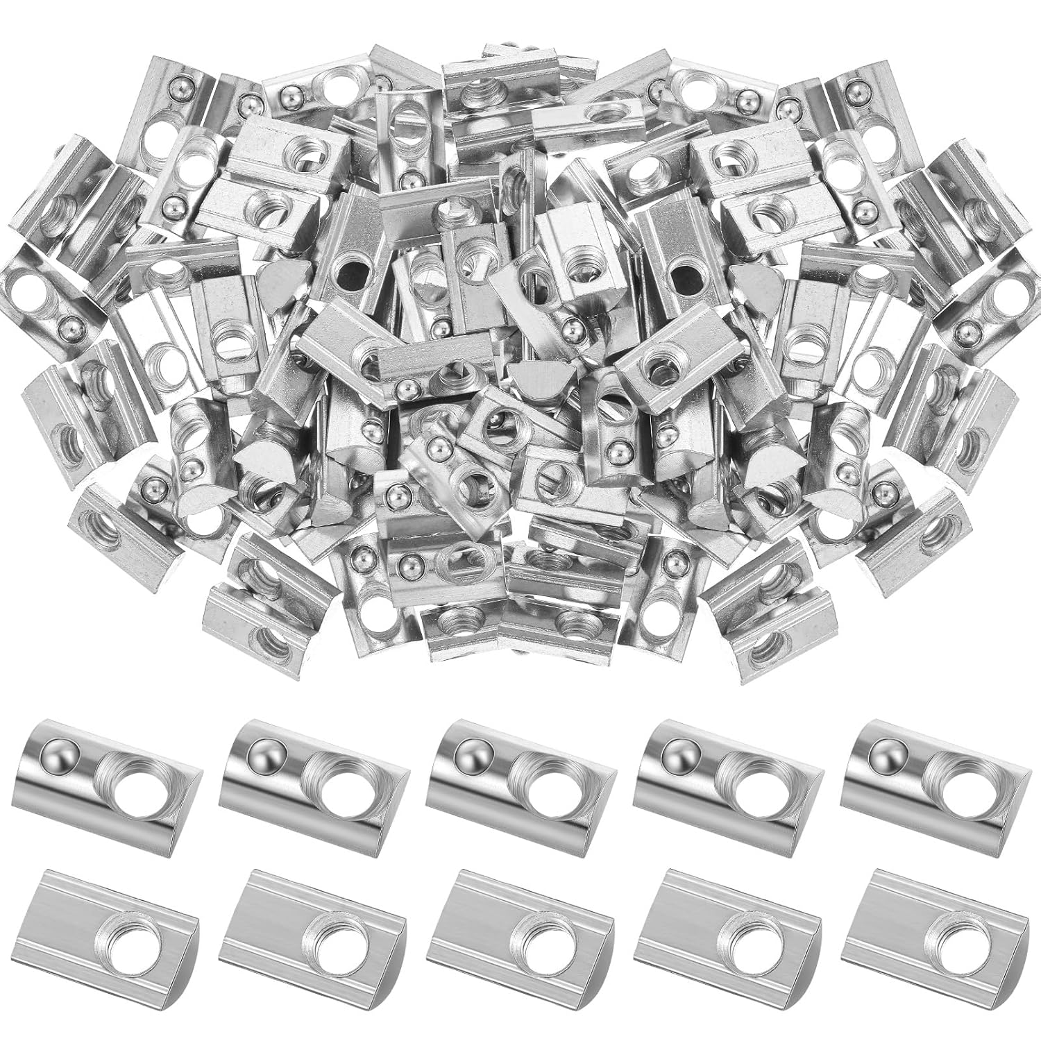
M5 roll-in T-nut, 2020
Spring-loaded M5 T-nut for 2020 extrusion (6 mm slot). Tilt it into the slot from the side, so it can go in anywhere along the extrusion. Every M5 button-head screw that goes into the extrusion screws into one of these.
Heat inserts
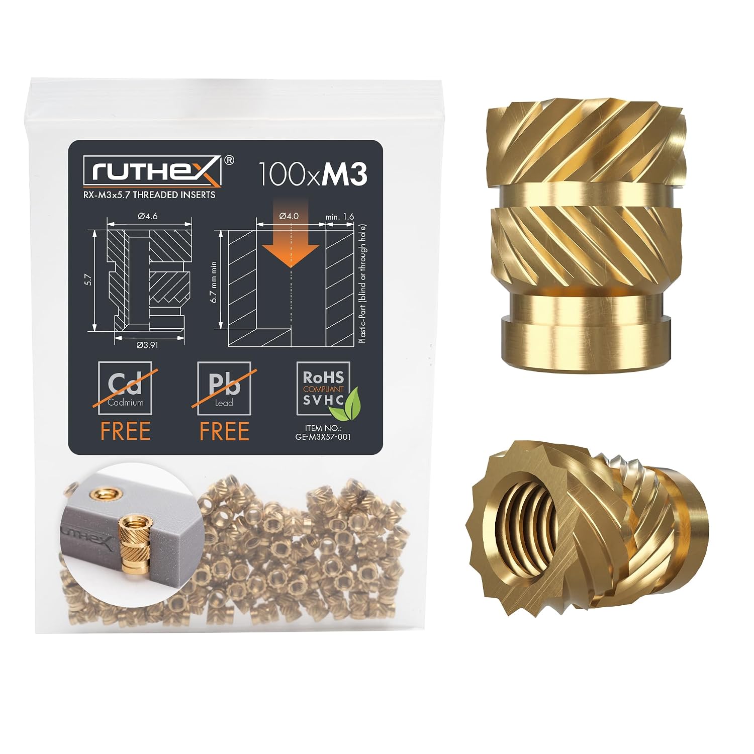
Ruthex M3 heat insert
ruthex RX-M3x5.7 brass heat-set threaded insert, 5.7 mm long. Melt it into a printed part with a soldering iron to make an M3 thread. Use it wherever a part calls for an M3 insert. Do not swap in the short M3S (RX-M3Sx4.0), which is a different part.
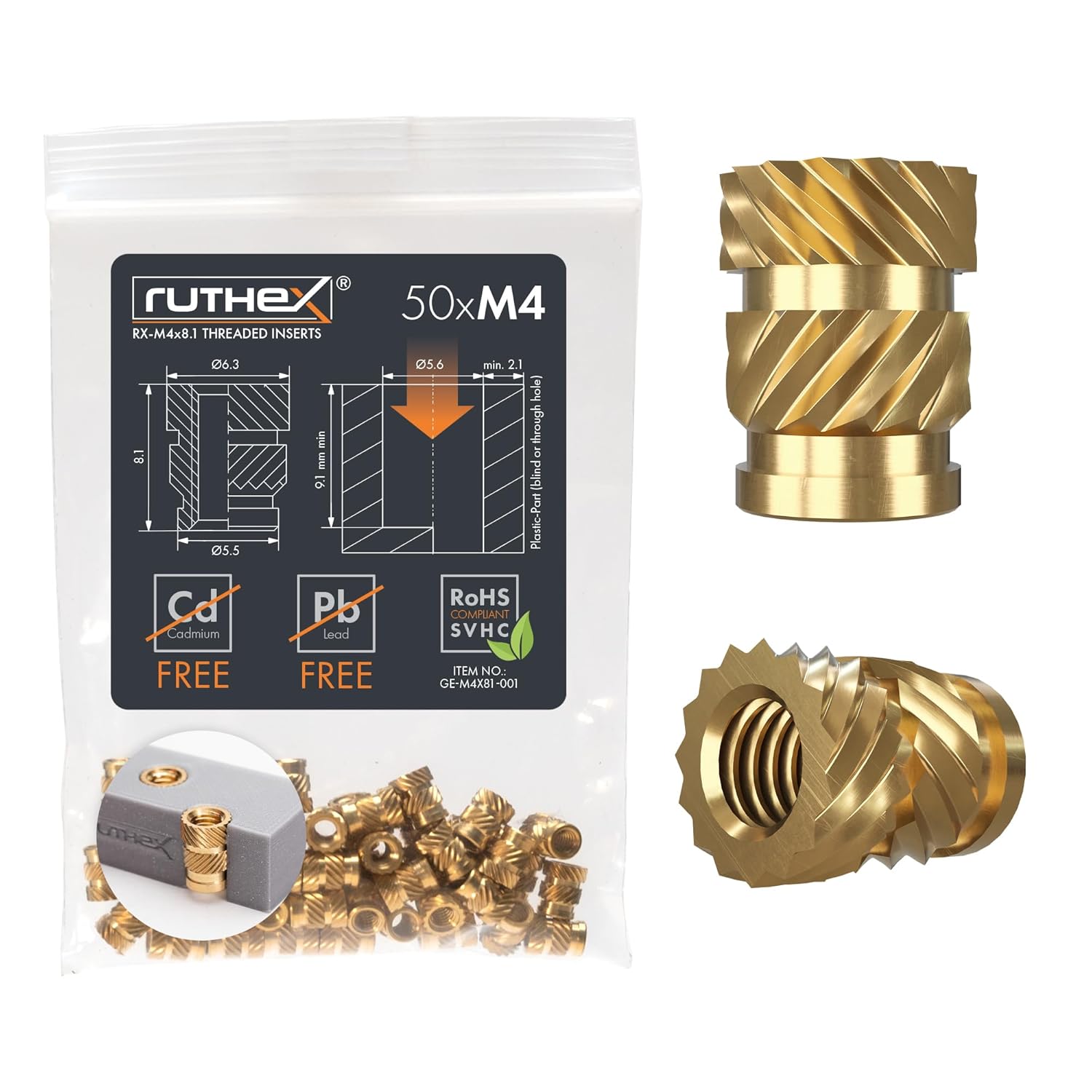
Ruthex M4 heat insert
ruthex RX-M4x8.1 brass heat-set threaded insert, 8.1 mm long. Melt it into a printed part with a soldering iron to make an M4 thread. It is the only M4 insert in the machine. Do not swap in the short M4S (RX-M4Sx4.0), which is a different part.
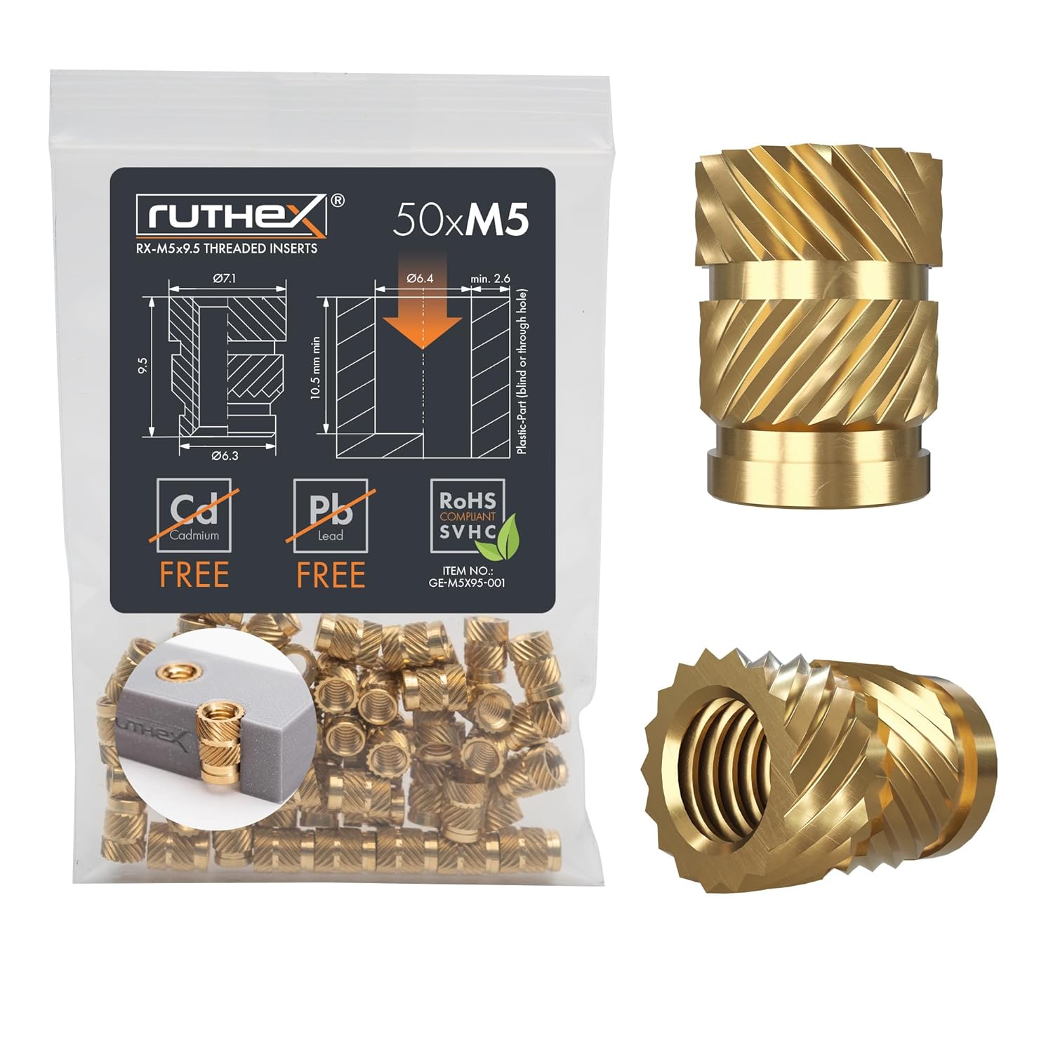
Ruthex M5 heat insert
ruthex RX-M5x9.5 brass heat-set threaded insert, 9.5 mm long. Melt it into a printed part with a soldering iron to make an M5 thread. Use it wherever a part calls for an M5 insert. Do not swap in the short M5S (RX-M5Sx5.8), which is a different part.
Cameras
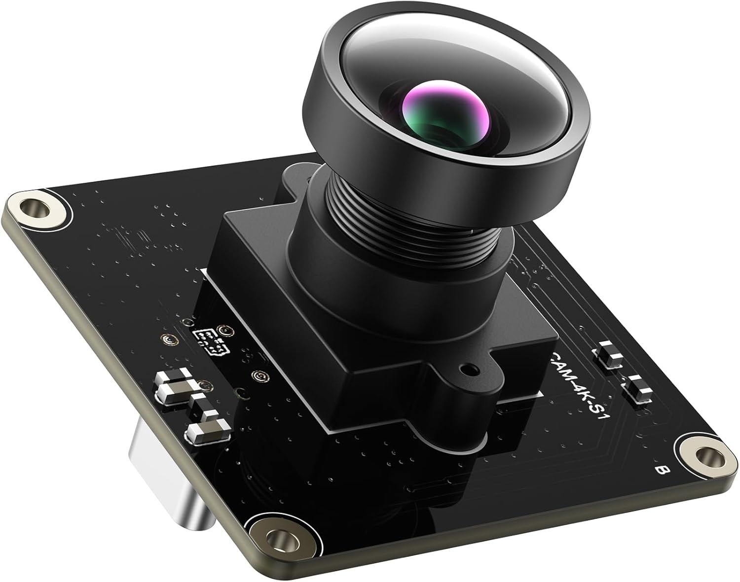
IMX415 4K camera module
Classification top camera. The innomaker IMX415 4K USB module.
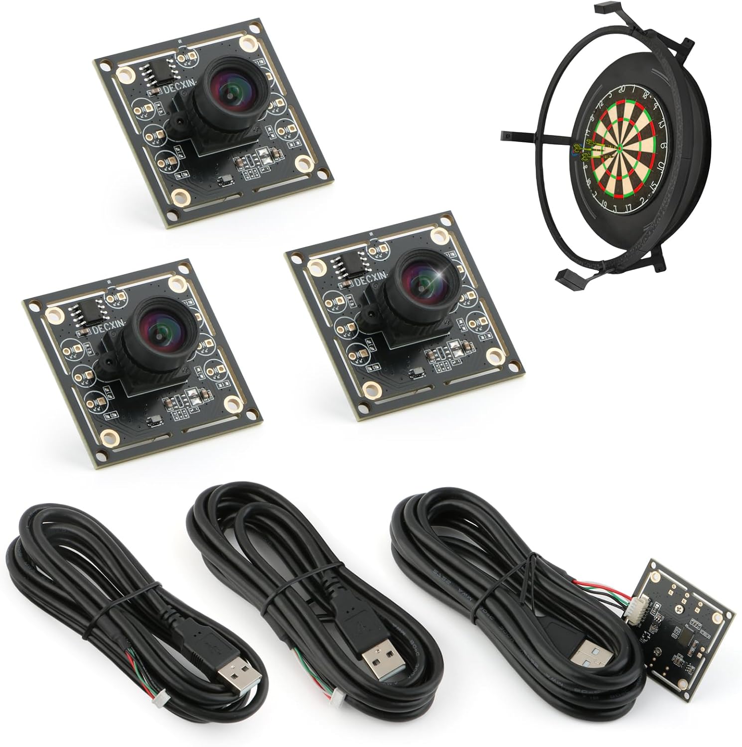
OV9732 720p Camera Module
C-channel and carousel drop plate detection cameras
Pulleys
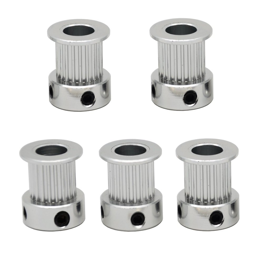
Timing pulley (20T, 8 mm shaft, 10 mm belt)
Timing pulley that sits on the stepper motor shaft and carries the chute gear. It has 20 teeth, an 8 mm bore and GT2 (2 mm) pitch, and takes a 10 mm wide belt. It arrives with two flanges, and the top flange is removed during assembly. It is fixed to the shaft with two M3 grub screws.
Wheels
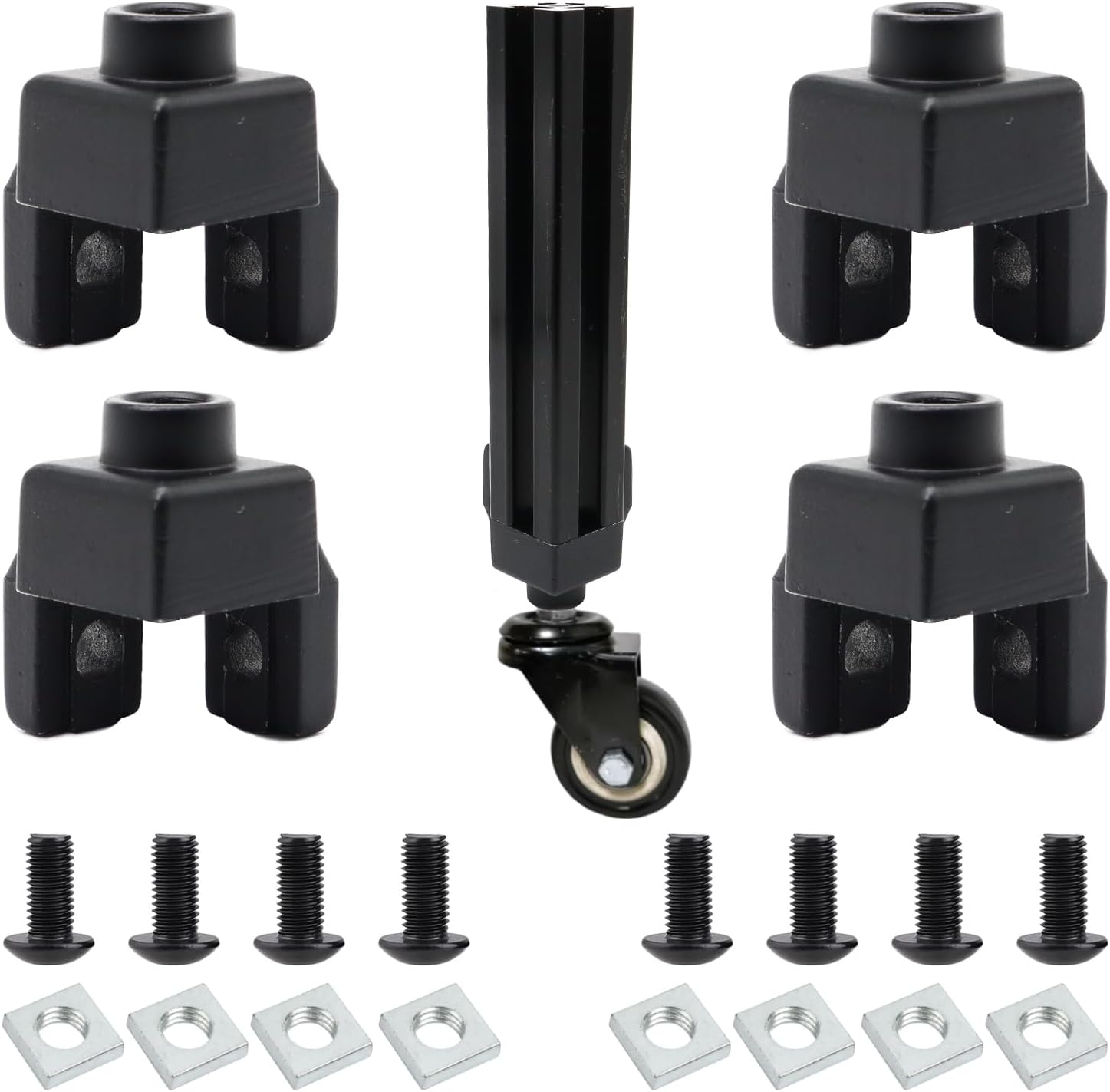
2020 M6 foot connector
Mounting foot that fits in the open end of each foot extension (piece D). It takes the caster's M6 stem so the machine can roll. You need 6, one per corner. It comes with its bolts and nuts.
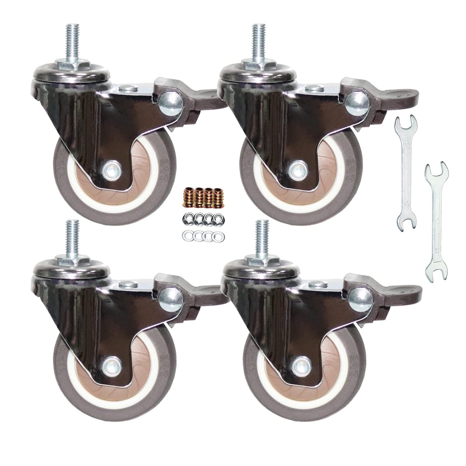
Swivel stem caster, M6 × 15 mm
Screws into the 2020 foot connector so the machine can roll.
Motors
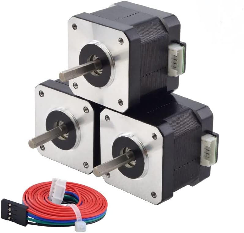
NEMA 17 stepper motor
C-channel and carousel drive motors
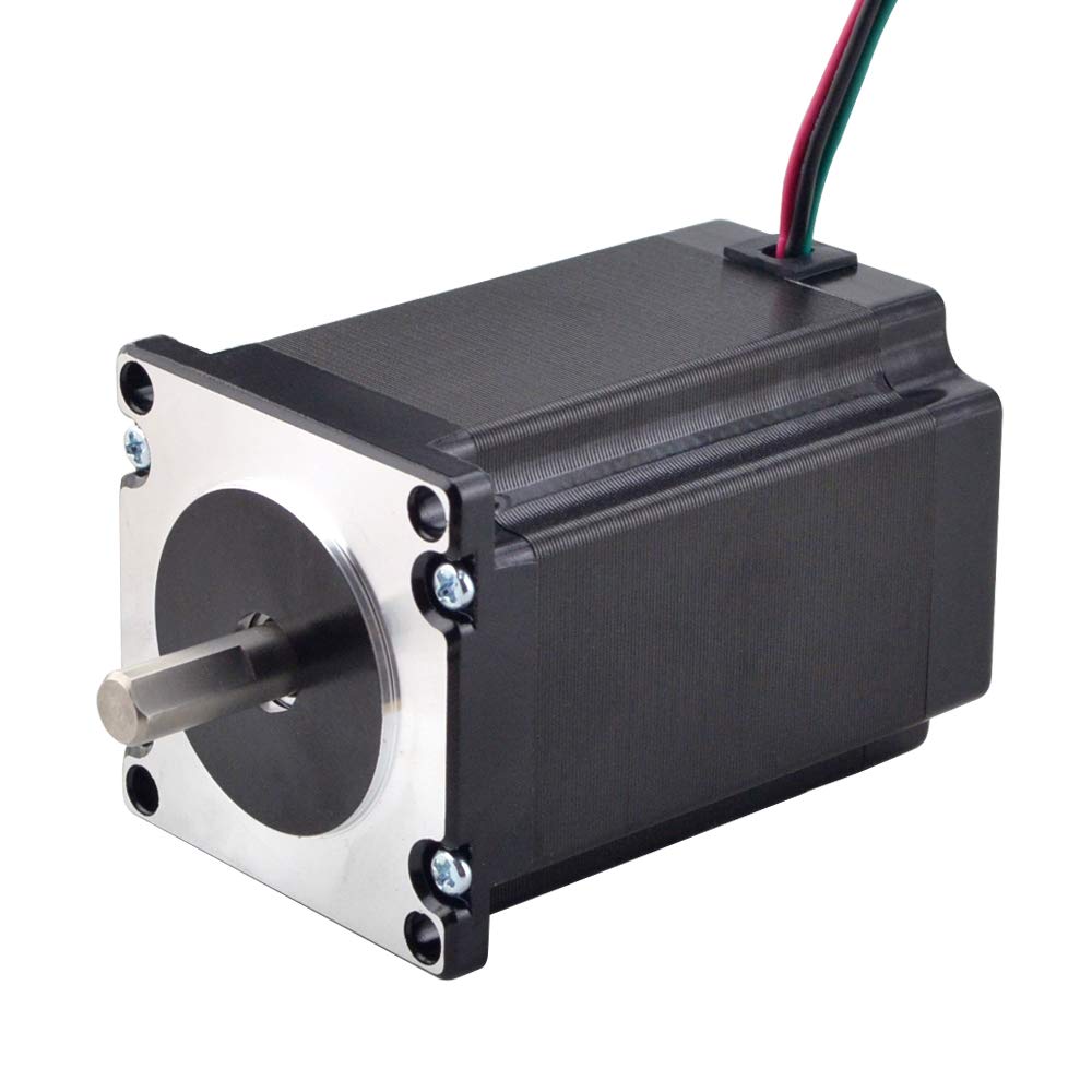
NEMA 23 stepper motor
Chute drive motor
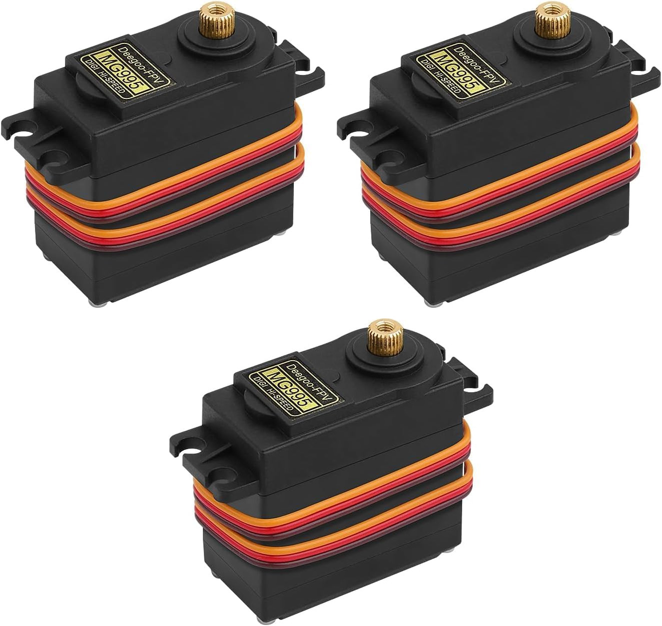
MG995 servo
Standard-size MG995 servo for the chute flap. Buy the 180° positional version, not the 360° continuous-rotation one. It comes with a set of servo horns.
Sold in a 360° continuous-rotation version under the same name and in an identical case. The flap needs the positional one, so check the listing says 180°.
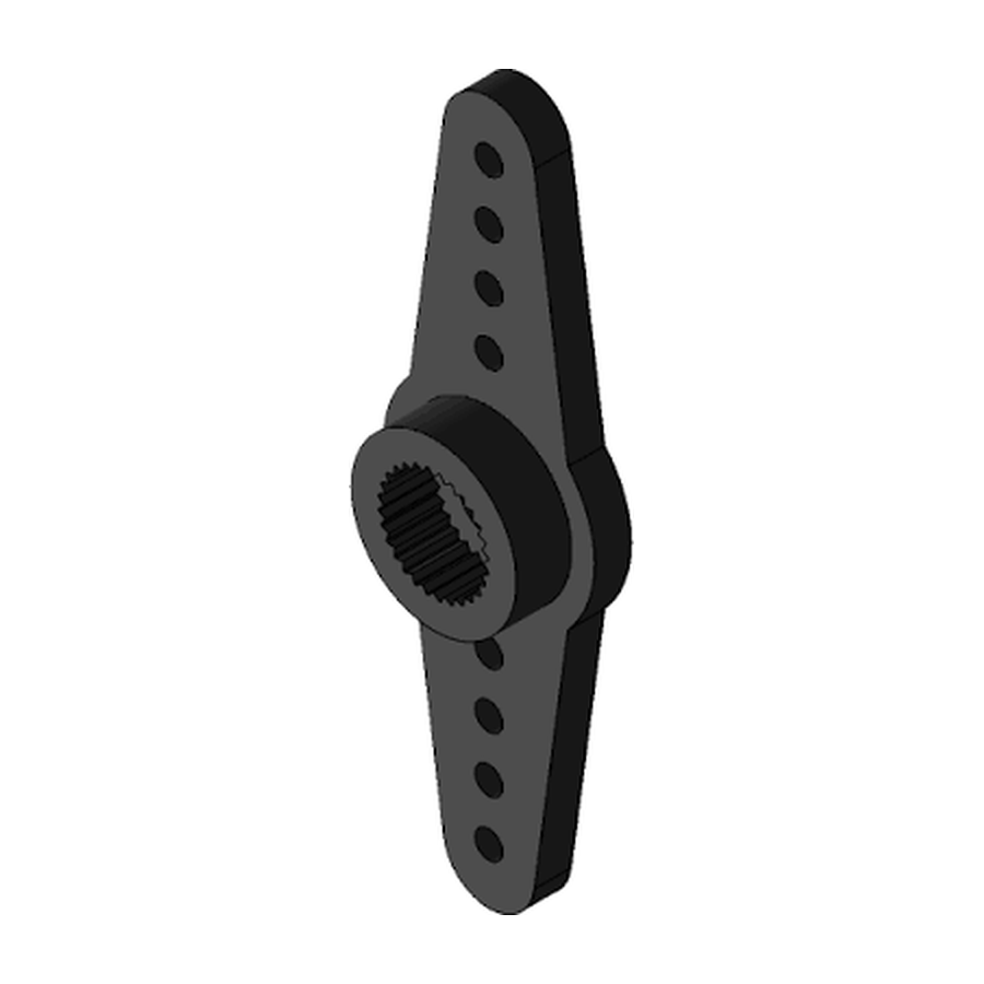
MG995 Servo Horn
Two-arm servo horn with a 25-tooth spline. It comes in the box with the MG995 servo, so you do not need to buy it. It is clamped between the two halves of the printed servo adapter when they are screwed together.
Ships in the box with the MG995 servo. Not sold separately, so it has no sourcing of its own here.
Bearings
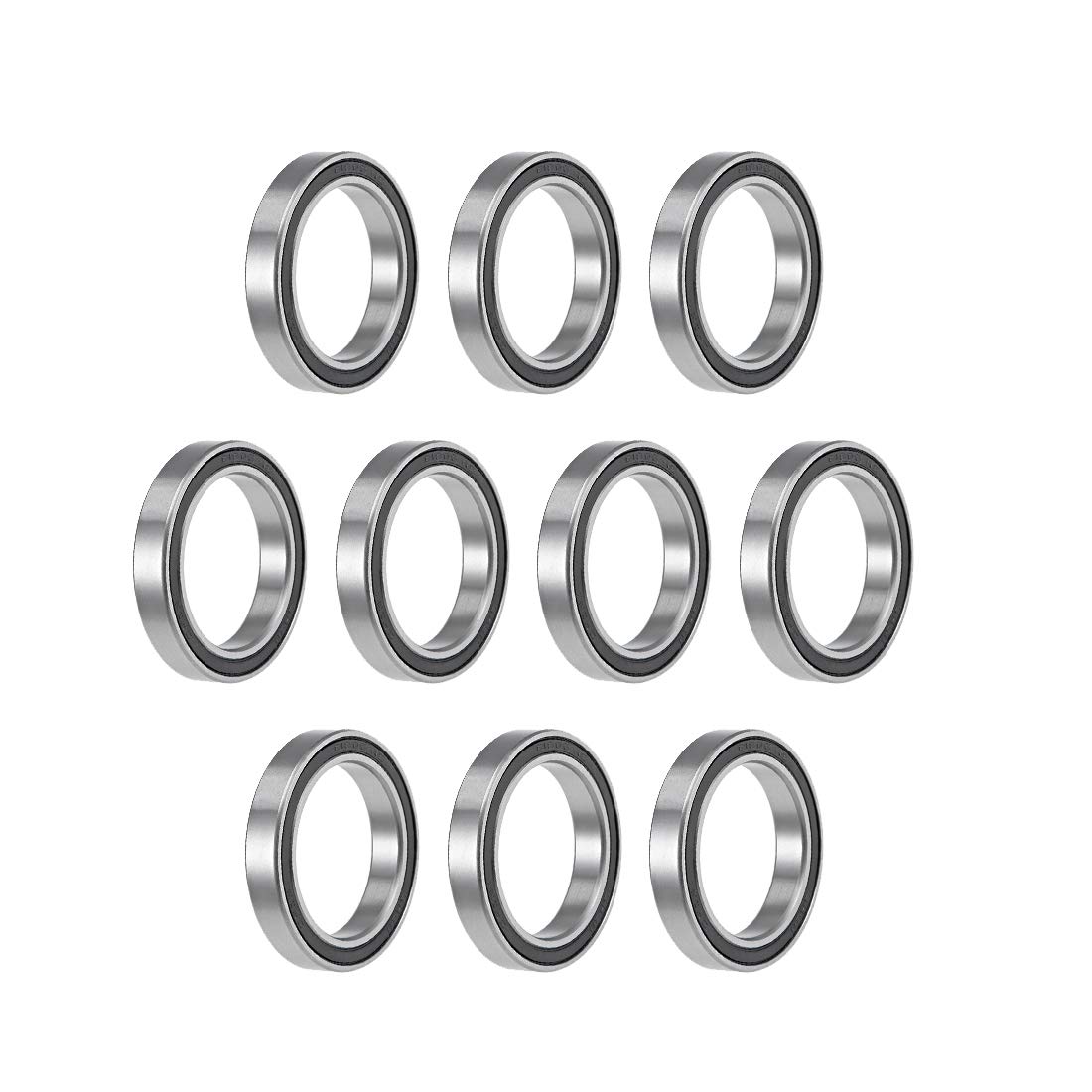
6806-2RS bearing
Pressed into the output gear of each C-channel rotor, one per channel.

608 2RS bearing
Pressed into the idler gear of each C-channel drive and into the chute stepper's idler gear. Four in the feeder and one in the top interface. No screw, no glue, no heat.
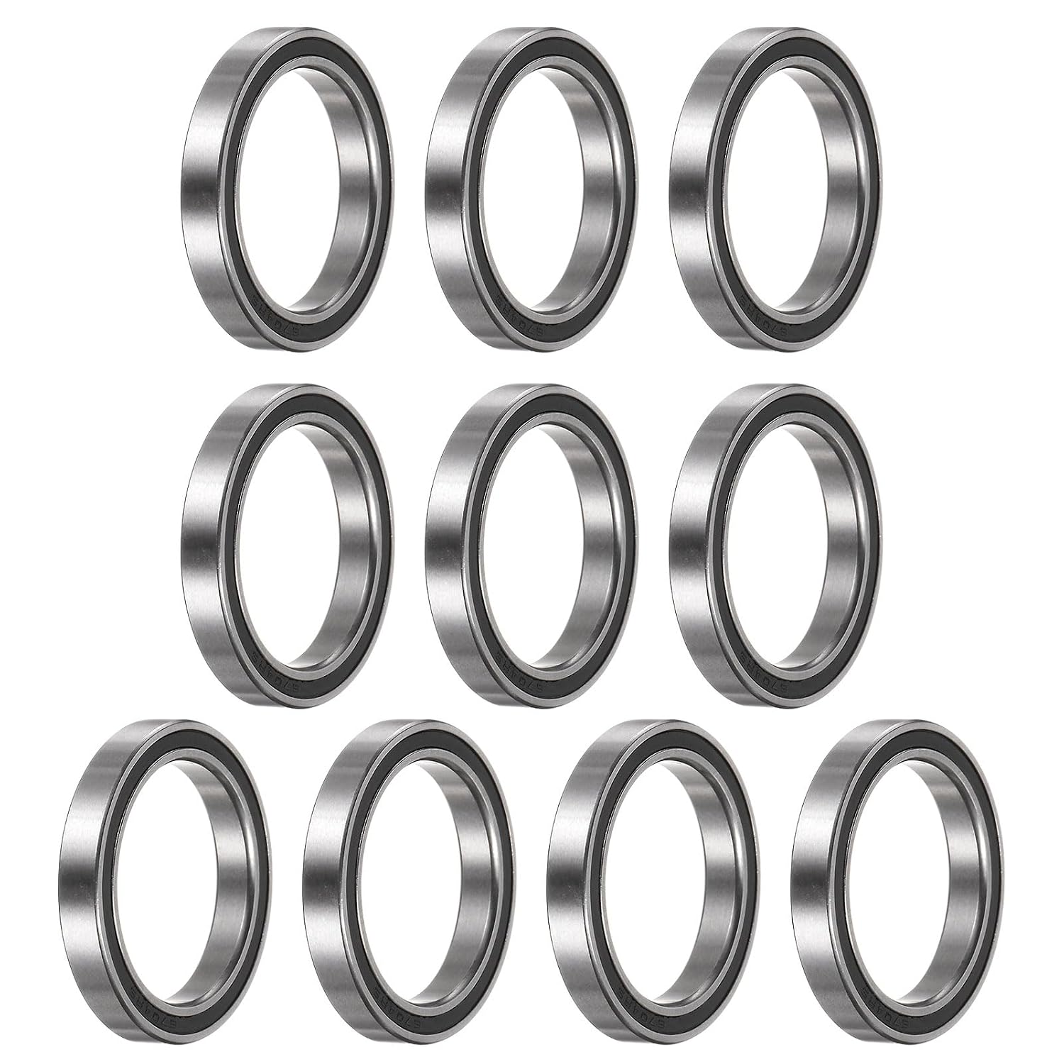
6704-2RS bearing
Thin sealed ball bearings for the chute flap.
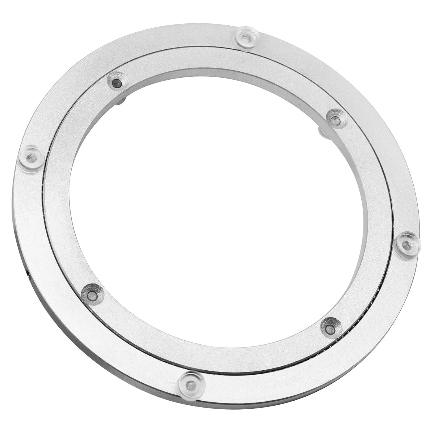
Lazy Susan
The bearing either end of the distribution stack: one in the top interface between the chute mount and the upper fixed section, one in the bottom interface.
Computer
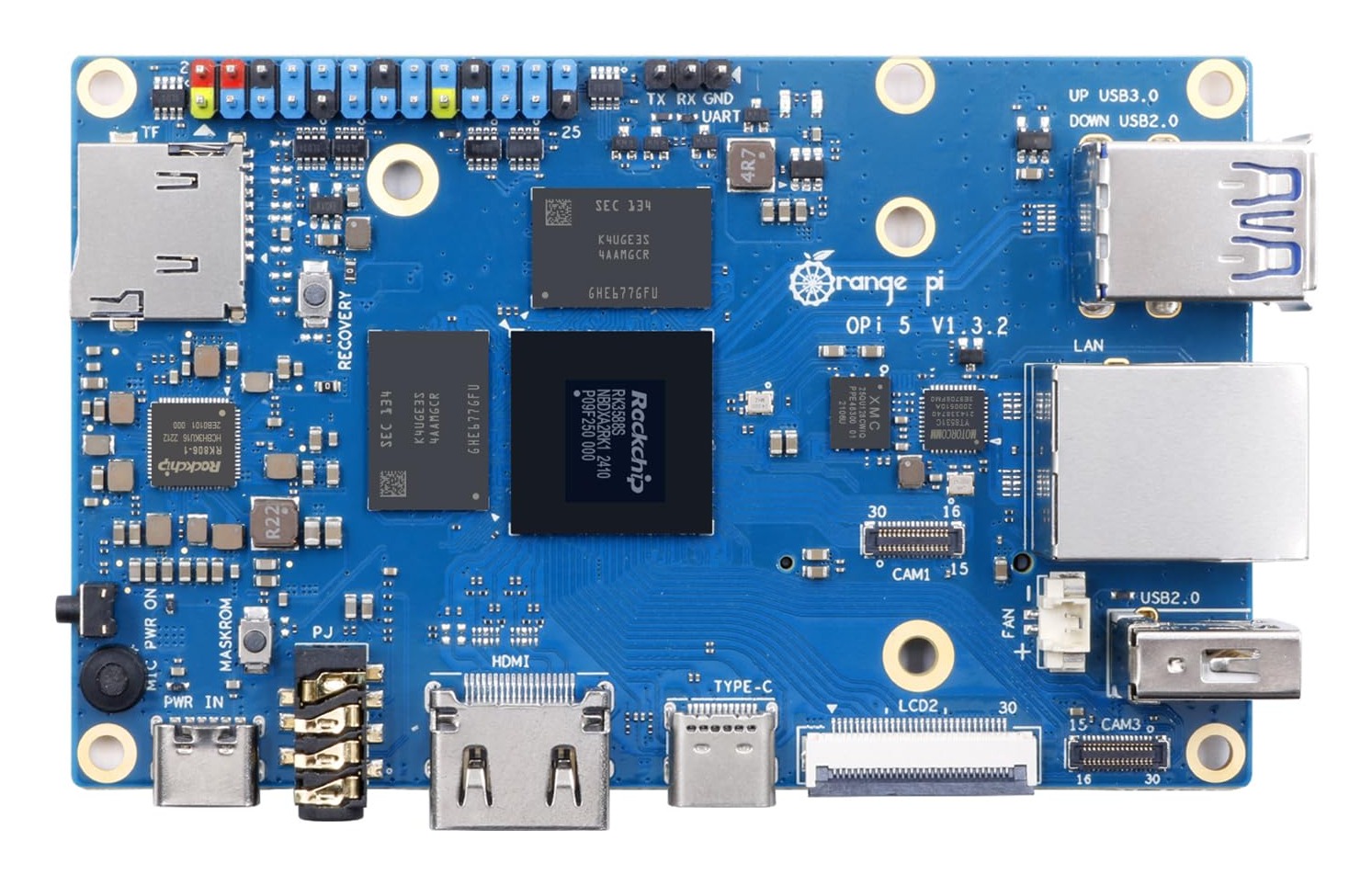
Orange Pi 5
The computer that runs the machine's software. Buy the Orange Pi 5, 8 GB: SorterOS, the ready-made image, is built for it. A Raspberry Pi 5 also works, but it needs the manual Linux install instead of the ready-made image.
Buy the plain Orange Pi 5, 8 GB. The 5 Plus, 5 Pro, 5 Max and 5 Ultra are separate boards rather than options on this one: none of them share its mounting-hole pattern, so the printed housing's posts do not line up, and the WiFi module listed in this catalog fits the plain 5 only. The 5B is not supported either: it does fit the housing's posts, but SorterOS is built from the plain 5's image and there is no 5B build.
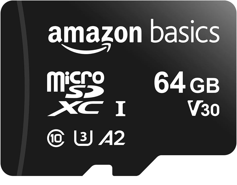
32gb+ Micro SD Card
The card SorterOS runs from, in the Orange Pi's microSD slot. Buy a 32 GB or larger high-endurance card from a name brand such as SanDisk or Samsung. SorterOS writes to the card all day, and cheap cards corrupt.
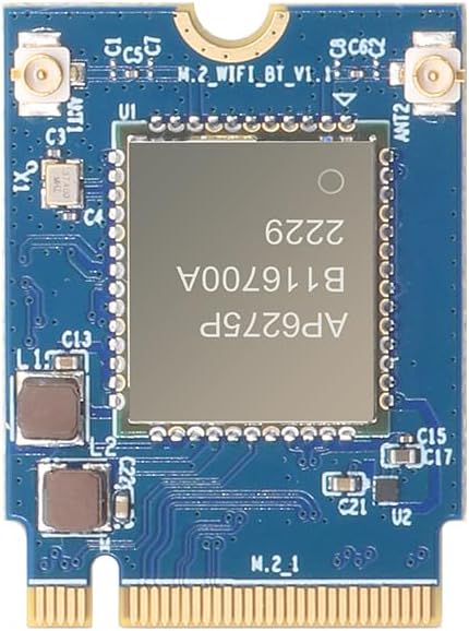
Orange Pi 5 WiFi 6 + Bluetooth module
WiFi and Bluetooth for the Orange Pi. Optional.
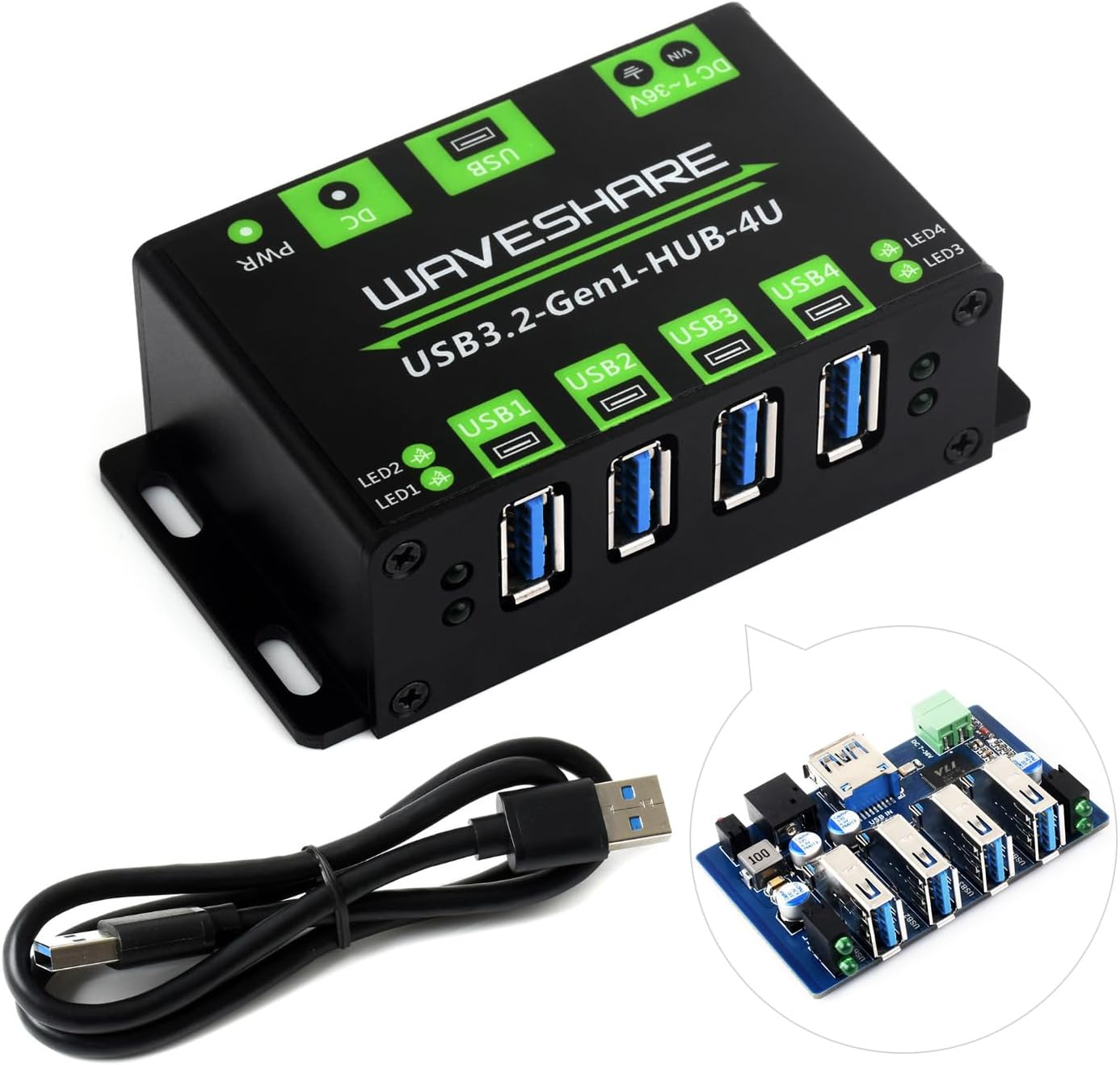
Powered USB Hub - 24v - 4 ports
The powered USB hub that connects the cameras and the Pico to the Orange Pi. It runs on 24 V from the PSU, so the model matters (see note). Buy one.
The hub is fed 24 V, so it has to take 24 V DC in. Waveshare sell four hubs of this shape: USB3.2-Gen1-HUB-4U and USB3.2-Gen1-HUB-2IN-4OUT take 7 to 36 V and both work. USB-HUB-4U and USB-HUB-2IN-4OUT are 5 V only and will not run. Check the DC input range on the listing before you buy; the model is printed on the case. The hub clamp on the Orange Pi housing's roof is drawn around the USB3.2-Gen1-HUB-4U.
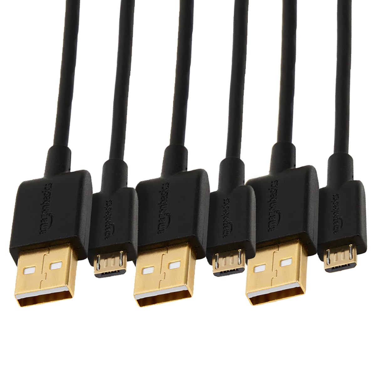
Micro USB Data Cable (U2)
Connects the Raspberry Pi Pico (U2) on the control board to the powered USB hub. Use a micro USB cable that carries data. Charge-only cables do not work.
USB Cables totally vary in quality. Ensure it supports data
Electronics
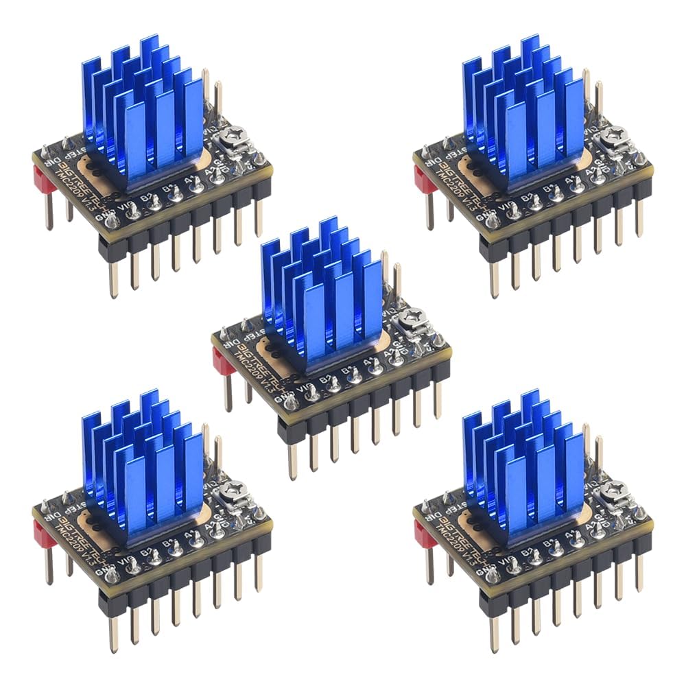
TMC2209 Stepper Motor Driver Modules
Stepper motor driver, one per stepper. A machine uses five. Buy the BigTreeTech TMC2209 V1.3 module (StepStick size, with heatsink, UART mode), or an identical StepStick TMC2209.
2.54 mm jumper cap
Shunt for the control board's MS1/MS2 headers, which set each TMC2209's address on its UART bus. 10 per machine, two per driver.
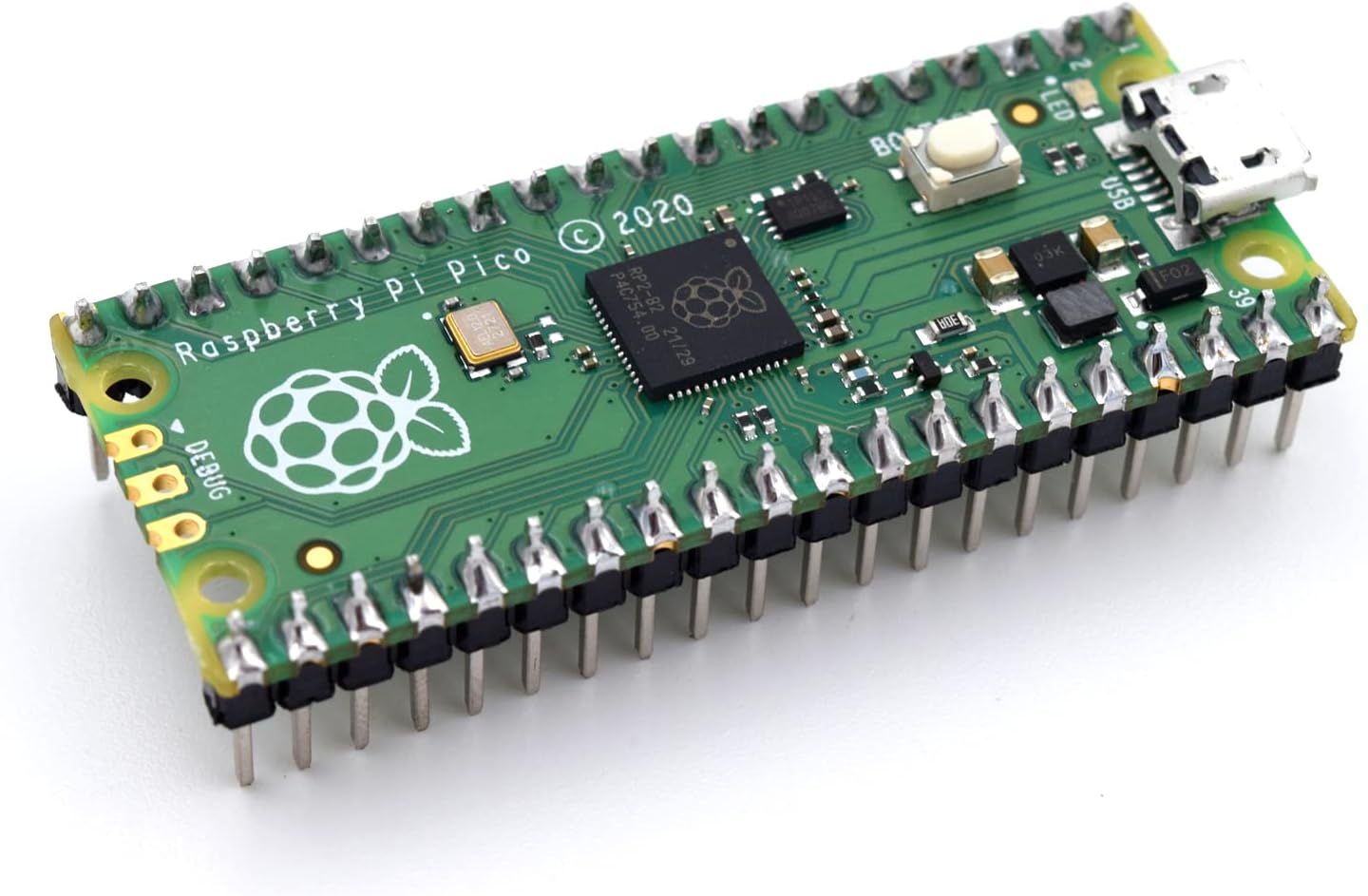
Raspberry Pi Pico with pre-soldered headers
Embedded MCU for controlling motors. Bought with its two rows of 20 header pins already fitted, ready to seat in the control board.
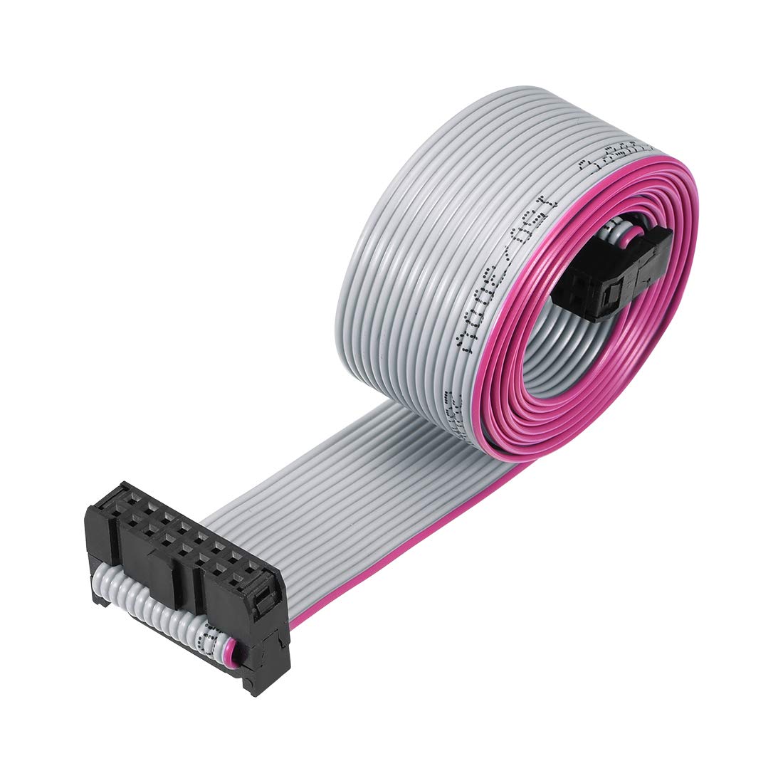 1.2m
1.2m IDC ribbon cable (RIB1), 16-pin (2×8), 1.2 to 1.5 m (47 to 59 in)
Ribbon cable (RIB1) from the control board's J17 to J3 on the first layer board. One per machine. Any length from 1.2 m (47 in) to 1.5 m (59 in) works, with a female socket on both ends.
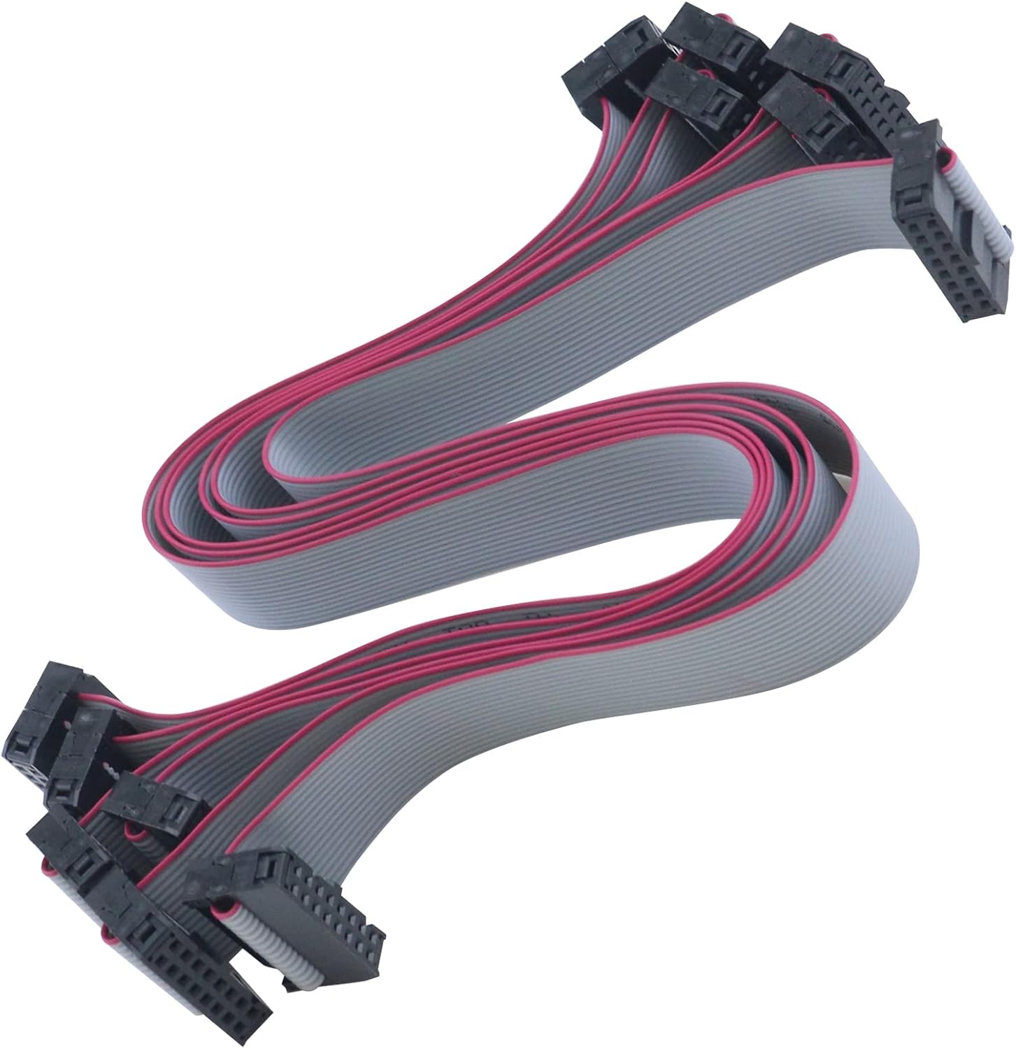 300mm
300mm IDC ribbon cable (RIB2), 16-pin (2×8), 300 mm (12 in)
Ribbon cable (RIB2) that links one distribution layer's J4 to the J3 of the layer below it. A machine uses 2 (3 layers) or 4 (5 layers). 300 mm (12 in) long, female socket on both ends.
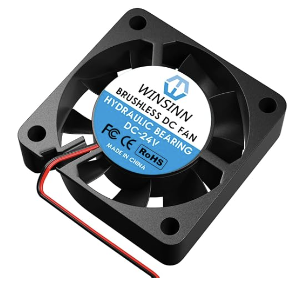
40 mm 24 V fan (WINSINN 4010)
40 x 40 x 10 mm axial fan, 24 V, on the control board housing cover, held against its vent by two printed fan retainers. Comes with an XH2.54 2-pin lead, which plugs straight into one of the board's LED ports. One per machine: the Orange Pi is cooled by its own heatsink fan instead.
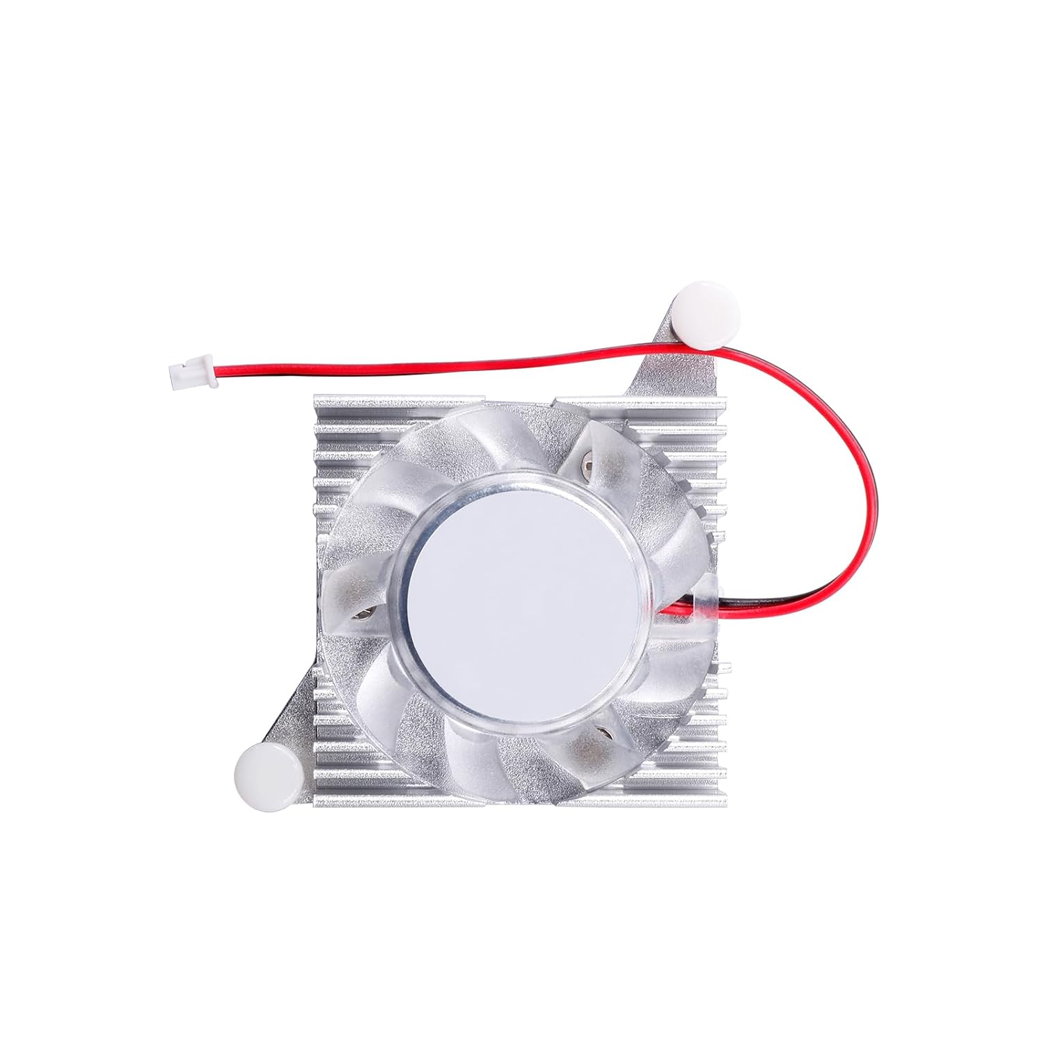
Orange Pi 5 heatsink fan (official)
Orange Pi's official aluminum-alloy heatsink and fan for the Orange Pi 5 (v1.3.2) and Orange Pi 5 Plus, which mounts directly on the SoC. 5 V DC, sleeve bearing, on two spring pins into the board's own holes.
Custom PCBs
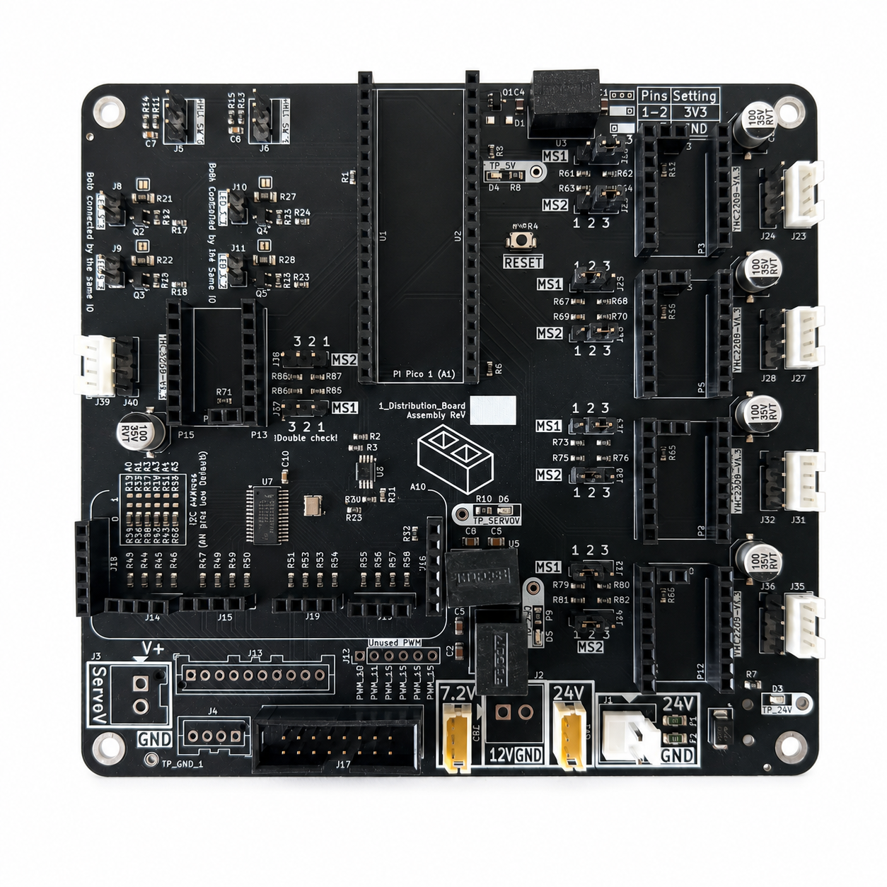
basically Embedded Control Board
In-house distribution/feeder control board: Pico, stepper drivers, servo and LED outputs. 1 per machine.
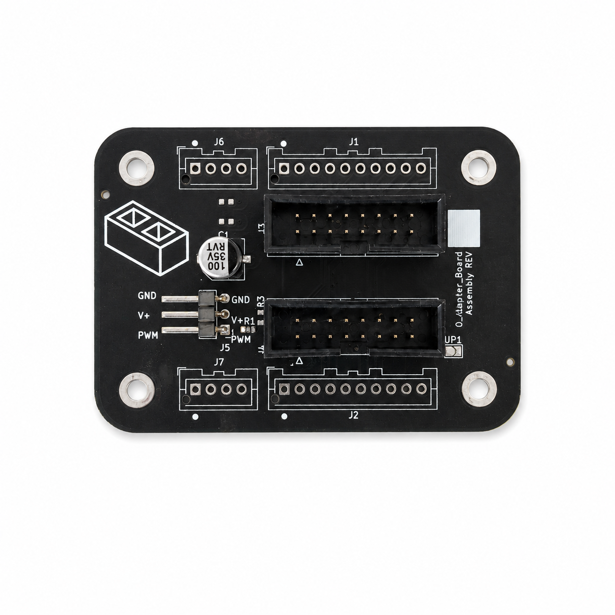
basically Layer Adapter Board
In-house adapter board that breaks out the control board's ribbon connectors for one distribution layer. 1 per layer.
Wire harness
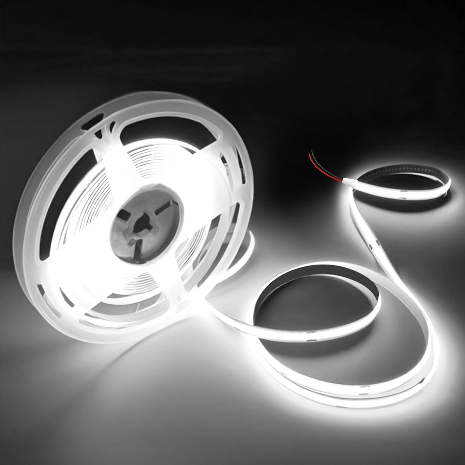
White/daylight LED strip - 24v
The light in a Camera lamp: two turns inside the reflector's skirt, held by the six LED hooks. Three per machine, all from one roll. Cut on the strip's printed marks, not to a measurement: the solder pads are at the marks, and the pitch differs from roll to roll.
Buy the 24 V roll: 5 m, 6000 K, 8 mm COB. The same listing also sells a 12 V one, and outside the US the link may not land on this product at all.
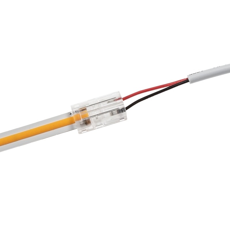
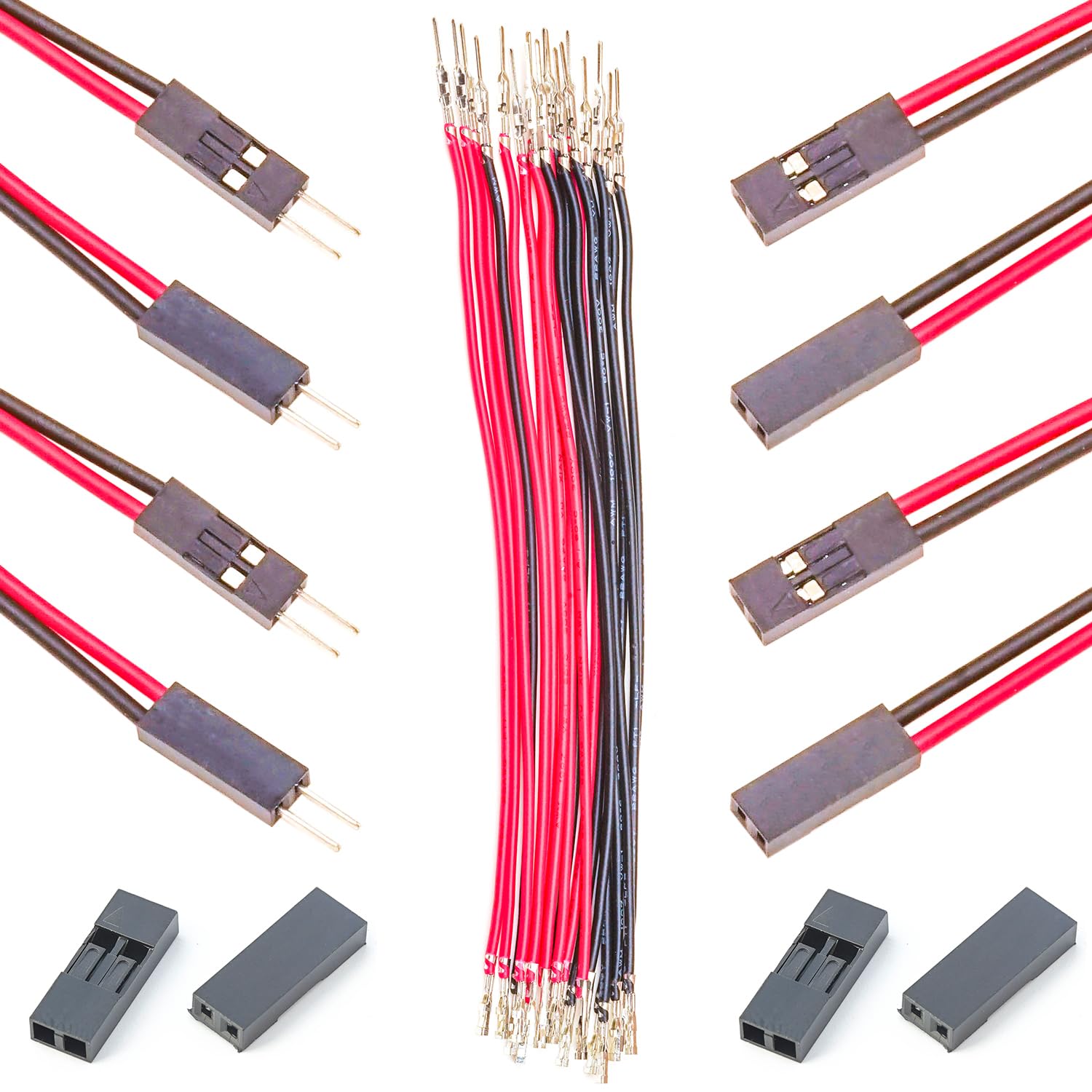
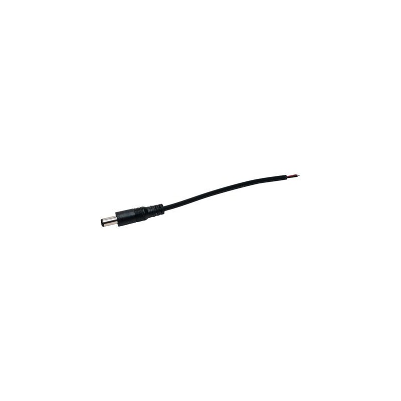
LED drop (L1 to L3, L1p to L3p)
Assembly CrimpingSoldering5 parts · click to expand
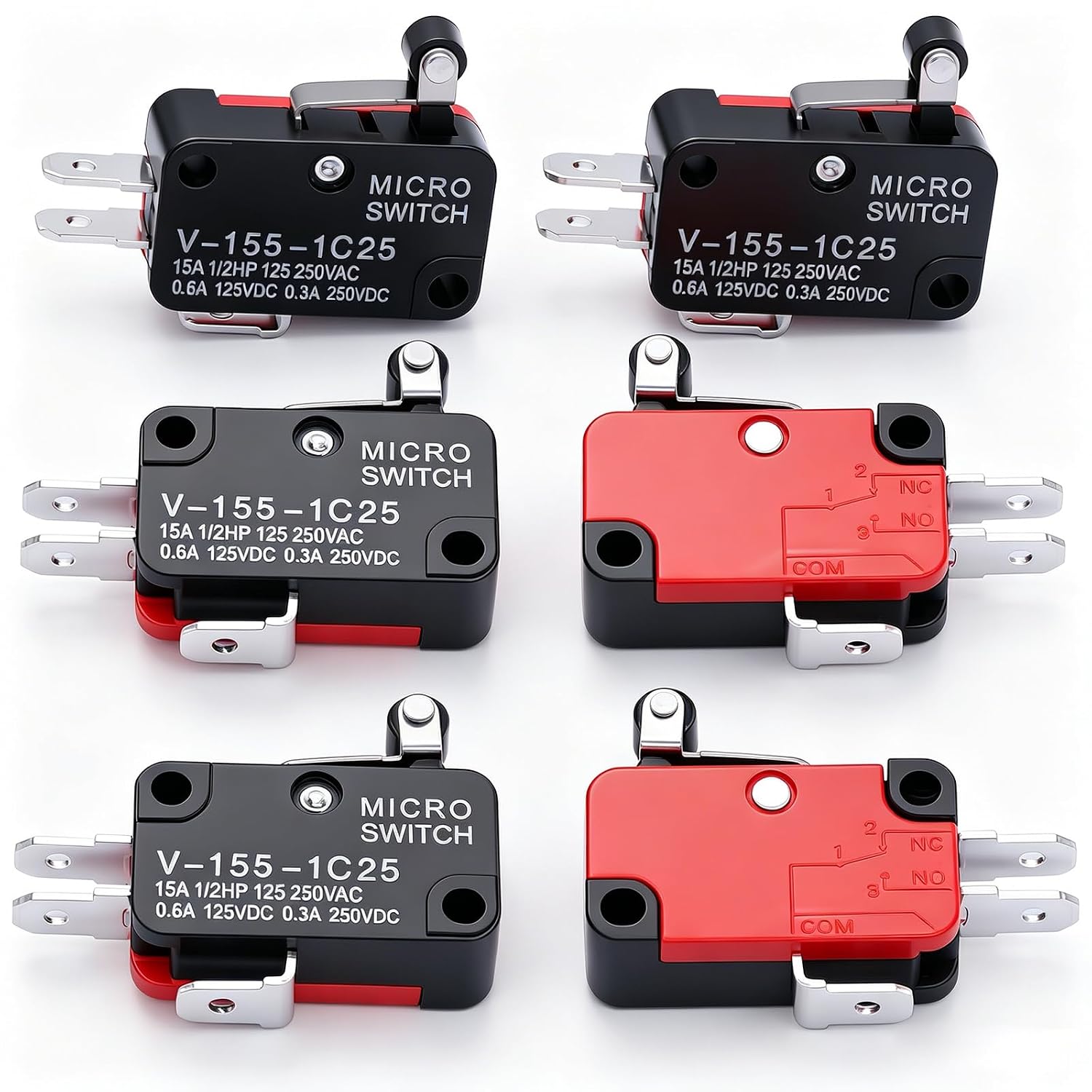
Roller lever limit switch (V-155-1C25)
Roller-lever microswitch, part number V-155-1C25. It tells the machine when the chute is at its home position. One per machine.
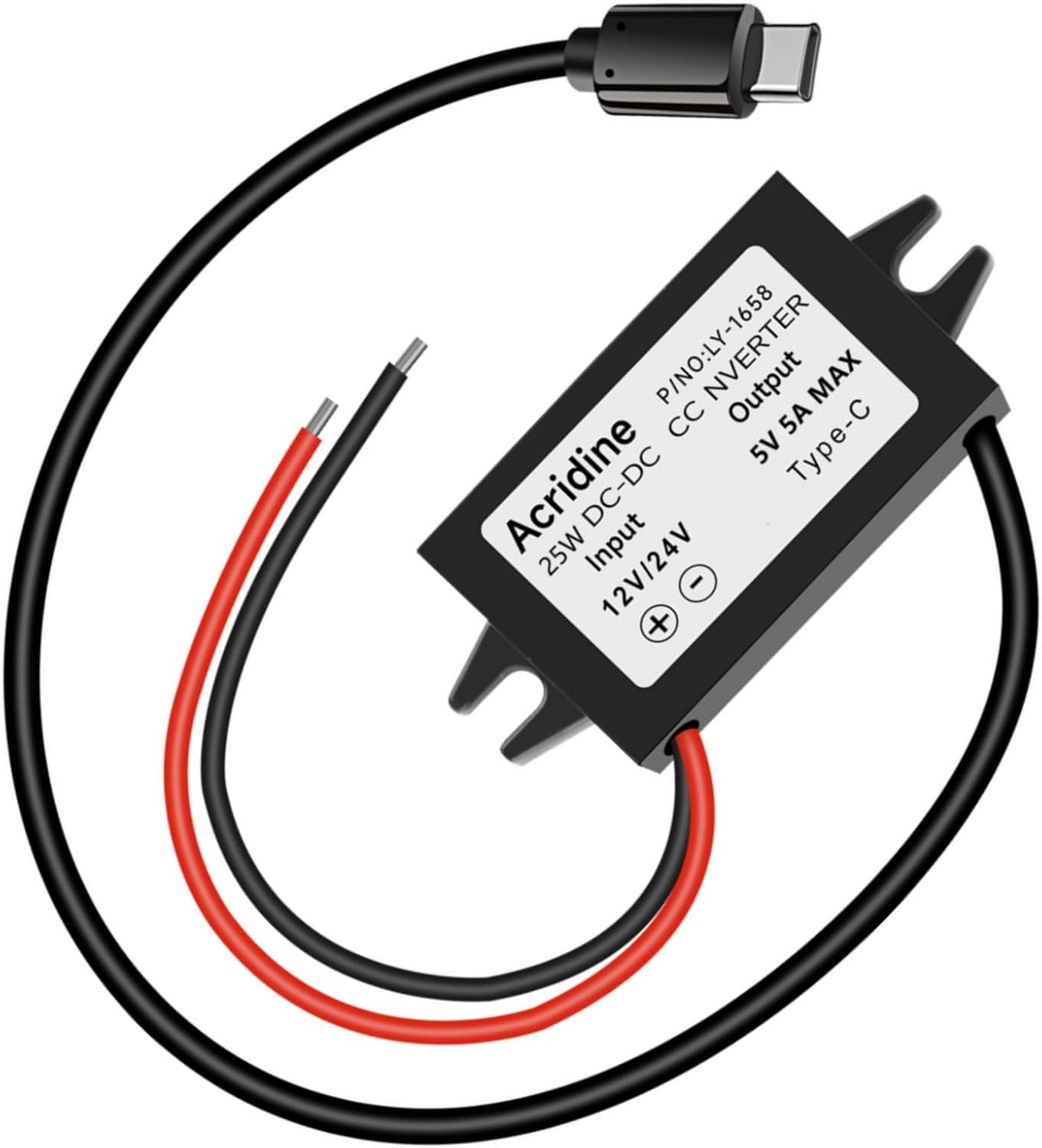
24 V → 5 V USB-C buck converter
Powers the Orange Pi from the 24 V PSU.
24 V board feed (W1)
Assembly CrimpingSoldering4 parts · click to expand
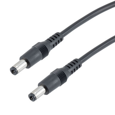
DC lead (W2, bought), 5.5 x 2.1 mm male to male, 610 mm (24 in)
The alternative for the powered USB hub's 24 V lead, W2, when the Orange Pi housing is mounted too far from the PSU box for a moulded barrel plug's own lead (about 310 mm (12 in)) to reach the hub's screw terminal: a ready-made lead with a 5.5 x 2.1 mm barrel plug at each end and 610 mm (24 in) of 22 AWG (0.33 mm²) between them. One end goes into a PSU box jack and the other into the hub's own jack. It is wired plug to plug, so the centre pin stays positive at both ends. Nothing is made or joined. Buy it only if you take that route; it is not on the machine's parts list otherwise.
5.5 x 2.5 mm leads look identical and do not mate: the 0.4 mm is on the centre pin. Check the pin size on the listing, not the outside diameter. Any male to male 5.5 x 2.1 mm lead of 22 AWG or thicker and centre positive does.
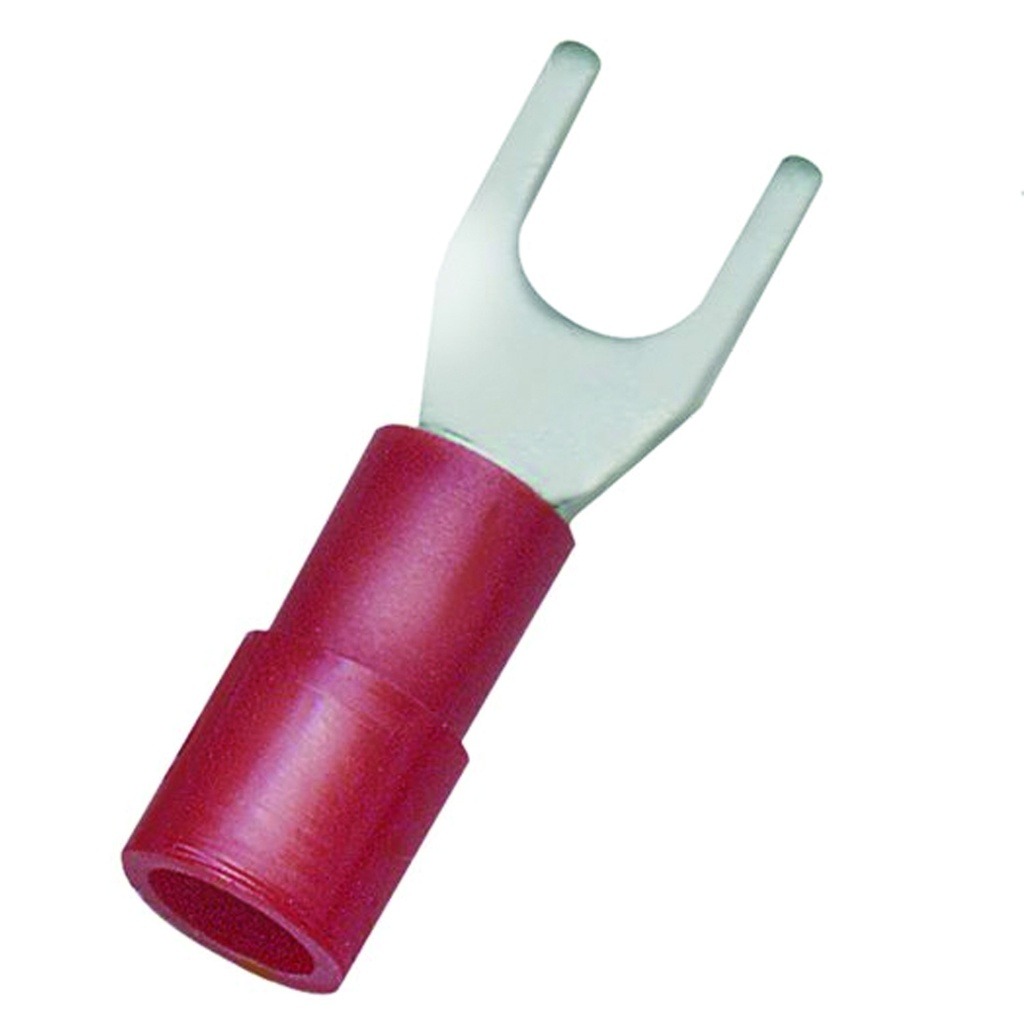
PSU output pigtail (PJ1 to PJ3)
Assembly Crimping2 parts · click to expand
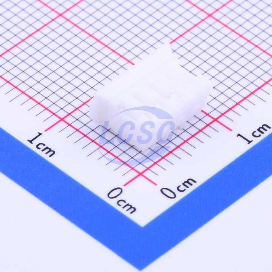
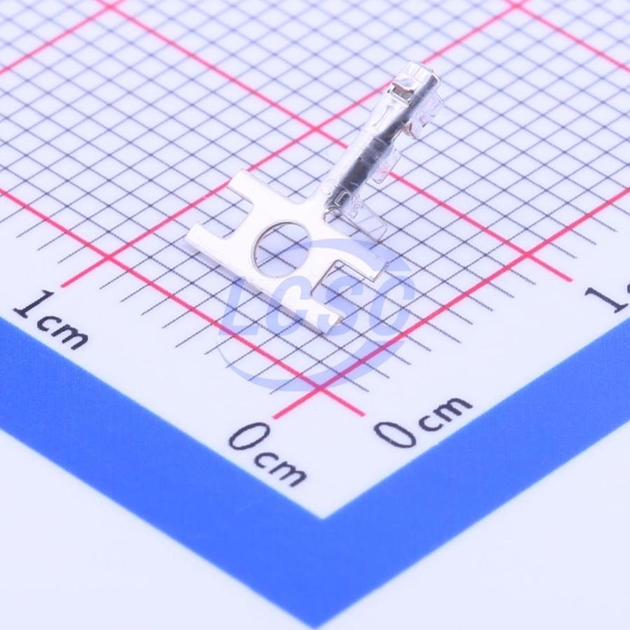
Channel stepper cable (S1 to S4)
Assembly Crimping2 parts · click to expand
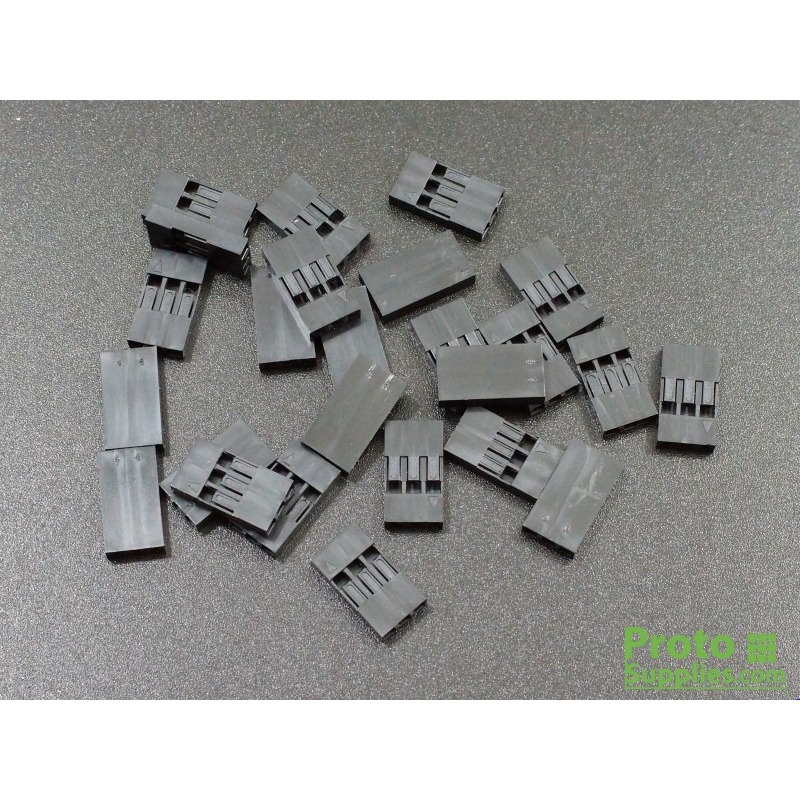
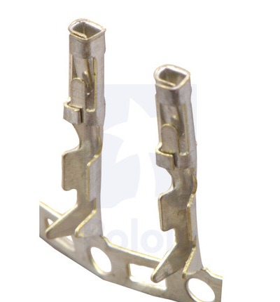
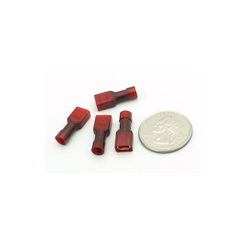
Limit switch cable (LIM)
Assembly Crimping3 parts · click to expand
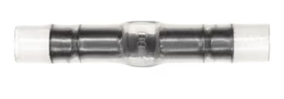
Chute stepper cable (CH)
Assembly CrimpingSoldering3 parts · click to expand
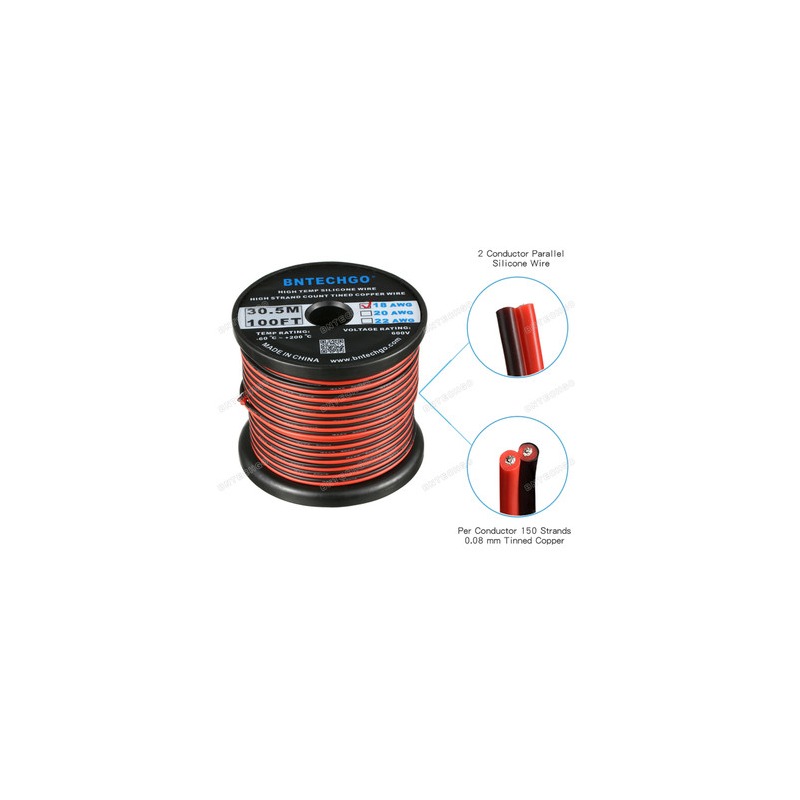
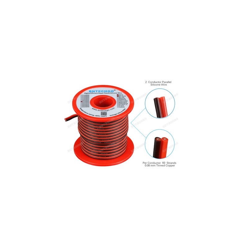
Hook-up wire, 18 AWG (0.82 mm²), 2-conductor red and black
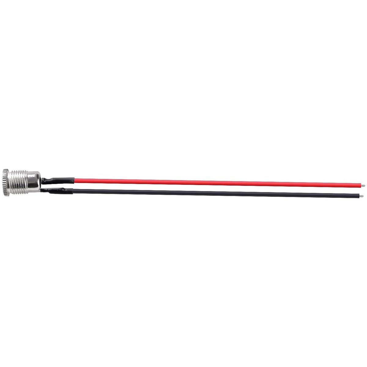
The heavy gauge in the machine: the three PSU output pigtails (PJ1 to PJ3) inside the box, and W1, the 24 V feed to the control board. A bonded red and black pair is easiest, since the polarity is then obvious at both ends.
The panel-mount jacks normally arrive with their 100 mm (4 in) leads attached, which leaves only W1's 920 mm (36 in) to make.
Hook-up wire, 22 AWG (0.33 mm²), 2-conductor red and black
The wire for the chute limit switch cable (LIM), and for extending the Orange Pi converter's input wires if they are shorter than 100 mm. The USB hub's 24 V lead (W2) is a barrel plug on its own short lead (or a bought lead), and the LED drops are bought Dupont cables and barrel plugs on their own leads, so none of those takes this wire. Making your own Dupont cable (L1 to L3) for a lamp is the one other use.
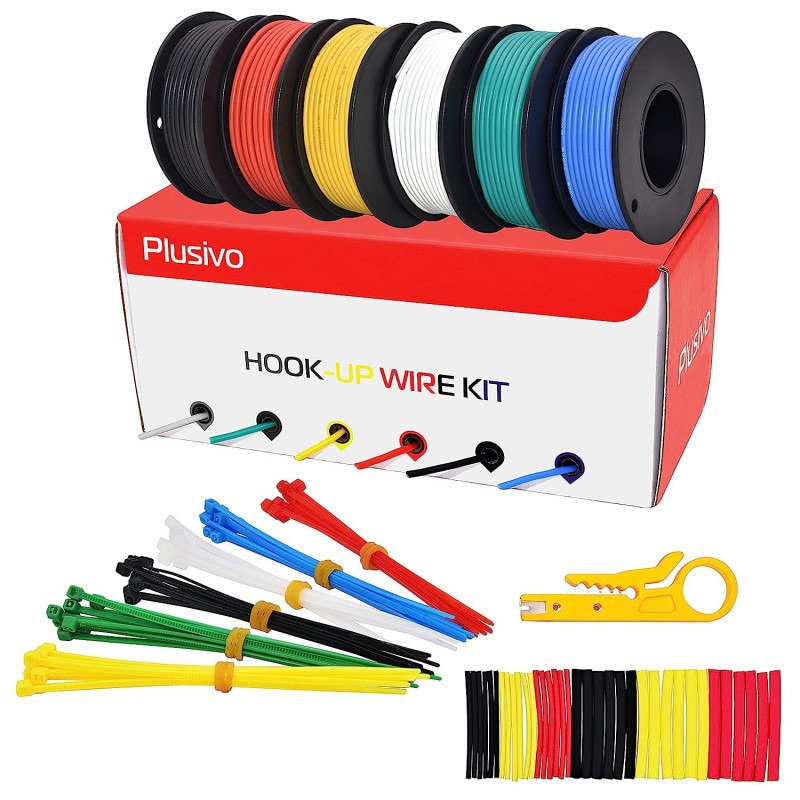
Hook-up wire, 24 AWG (0.20 mm²), four colours
The tail of the chute stepper cable (CH): a four-wire bundle in four colours, which is how you keep the coil pairs straight.
24 AWG (0.20 mm²) is not a choice: it is the heaviest wire the JST PH contacts accept. Do not go up a gauge for these.
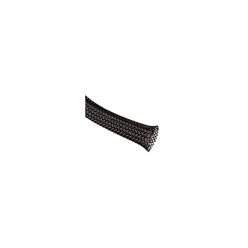
Braided cable sleeving, 1/4 in
Optional. Holds the wires of each lead you make (W1, W3, LIM, CH, S1 to S4, L1 to L3) together as one bundle, and protects them where they run along the frame, so a metre of loose wire does not end up spread across the machine. Every lead works without it.
Buy PET braid in 1/4 in (6 mm) size, which is what the links are. The harness drawing sleeves only the four S bundles; sleeving the other leads is a choice, as a way of securing the cables.
Power supply
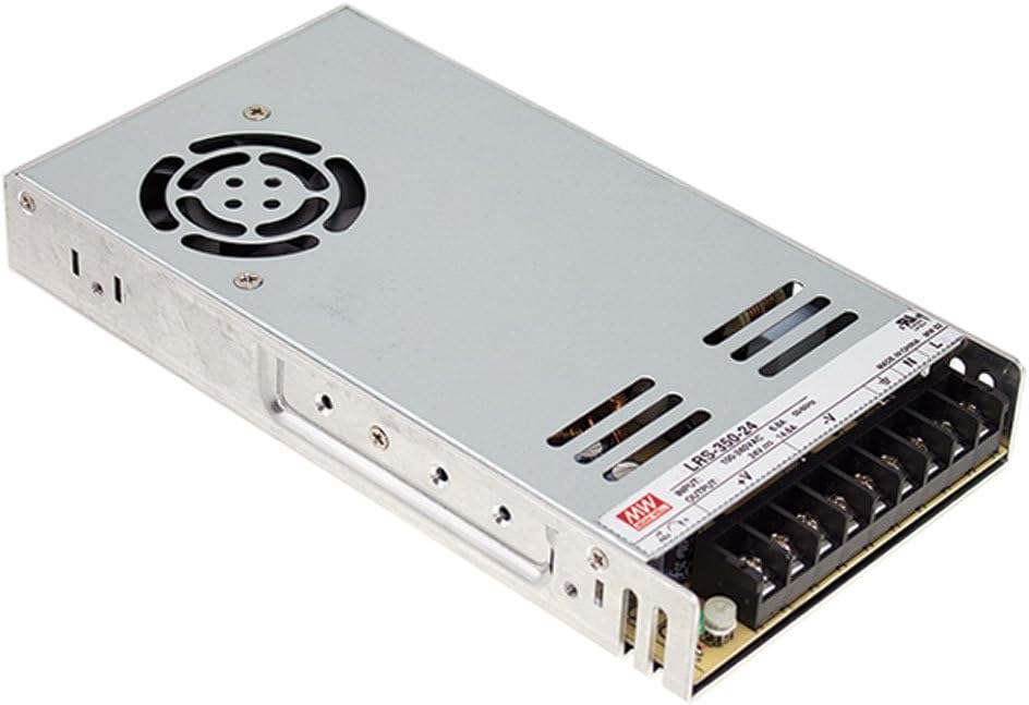
24 V PSU, 350 W (Mean Well LRS-350-24)
Mean Well LRS-350-24, the 24 V 350 W power supply for the whole machine. Buy this exact model, do not substitute. Before first power-up, set the slide switch on its side to 115 V (US) or 230 V (EU).
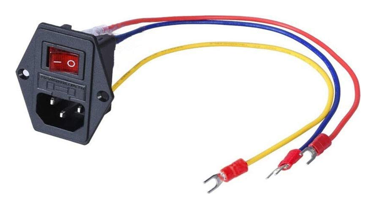
IEC C14 inlet, switch + 10 A fuse
Mains inlet for the PSU: switched, fused, pre-wired.
Its red and blue leads are not consistent between units: both have arrived with the live on either colour. The fuse and the switch are in the live side, so pull the fuse and meter which lead loses continuity to its C14 pin, and land that one on the supply's L. Going by colour risks fusing and switching the neutral.
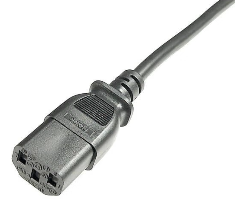
Mains lead (AC1), IEC C13 to wall plug
The mains lead (AC1) from the wall socket to the machine. The machine end is a C13 socket, which mates with the inlet's C14. The wall end is your local plug: US NEMA 5-15 or EU Schuko CEE 7/7. It is the cord a desktop PC or a monitor comes with.
Three core: the machine earths through this cable. 10 A or better, which matches the inlet's own fuse and is far more than the machine draws. It is listed so it is not forgotten at the end of a build, not because it has to be bought; most people have a spare one already.
Aluminum extrusion (2020)
 320mm
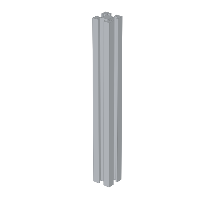
320mm Hex outer horizontal (A)
2020 aluminum extrusion, piece A, 320 mm long. Outer ring of every hex frame. Six per ring, on each bin layer and on the interface frame, all built to the same guide. Order it cut to 320 mm. Buy every extrusion piece from the same supplier in one order.
158mm Hex spoke (B)
2020 aluminum extrusion, piece B, 158 mm long. Inner ring of every hex frame. Six spokes per ring, on each bin layer and on the interface frame. Do not confuse it with the Interface spoke, long (E), which is 238 mm and belongs to the interface frame. Order it cut to 158 mm. Buy every extrusion piece from the same supplier in one order.
154mm Layer vertical support (C)
2020 aluminum extrusion, piece C, 154 mm long. Vertical support between two layers. One per corner, joining one hex frame to the next. Order it cut to 154 mm. Buy every extrusion piece from the same supplier in one order.
231mm Foot extension (D)
2020 aluminum extrusion, piece D, 231 mm long. Replaces piece C on the bottom layer. One D per corner runs from the caster up through that layer's corner to the layer above, so 6 per machine. Order it cut to 231 mm. Buy every extrusion piece from the same supplier in one order.
 238mm
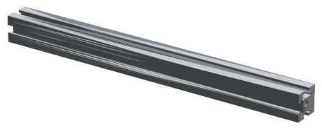
238mm Interface spoke, long (E)
2020 aluminum extrusion, piece E, 238 mm long. Spoke of the interface frame. One E is aligned with each Interface bracket. It is not part of a hex frame. Order it cut to 238 mm. Buy every extrusion piece from the same supplier in one order.
 274mm
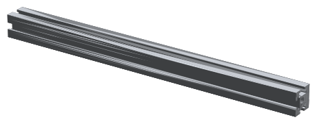
274mm Interface vertical support (F)
2020 aluminum extrusion, piece F, 274 mm long. Vertical support at the interface. One F per corner stands in an Interface bracket and runs down to the top layer. Order it cut to 274 mm. Buy every extrusion piece from the same supplier in one order.
228mm C-channel 1 support leg (J)
2020 aluminum extrusion, piece J, 228 mm long. Support leg for C-channel 1. C-channel 1 stands on three of these, held by their own weight, so this is 3 per machine. C-channels 2 and 3 use printed legs and need none. Order it cut to 228 mm. Buy every extrusion piece from the same supplier in one order.
As an Amazon Associate we earn from qualifying purchases. Open any part for a “Not affiliate” link to the same listing without the referral tag.